Thread Rating:
  • 0 Vote(s) - 0 Average
  • 1
  • 2
  • 3
  • 4
  • 5

Nathan's 37-690X
#31

The 37-690X lives!

[Video: https://www.youtube.com/watch?v=xos2MnVxe-c]

I finished the recap on the weekend but didn't have any luck getting anything at all out of it. That's the way it's been since the first time I brought it up on the variac after finishing the amp/power chassis.

So today I decided to trace through the entire amp/power chassis and make sure I hadn't made any dumb mistakes.
Well it didn't take long for me to discover that I had (of course).

I discovered this wire coming off the transformer and with its end hidden under one of the bakelite block.

That there's your problem!

[Image: https://farm2.staticflickr.com/1849/4392...7ea4_c.jpg]

I still traced through the rest of the chassis and then reconnected it and....

[Video: https://www.youtube.com/watch?v=p4UO7o4LPX0]

oh_yeah  oh_yeah   oh_yeah

What a relief to hear it working after going through the whole thing!

Status

Band 1 - Broadcast band works great.
Band 2 - Silent (as expected)
Band 3, 4 - Static
Band 5 - Silent (uh oh)

We'll see once I get things aligned but I would still expect to hear something on Band 5.

Sound out of both tweeters as well as the woofer obviously.

Volume control works well.
IF control works but is noisy.
Magnetic tuning - didn't try yet.
Bass control had no effect.

Audio Choke (Bass amplifier)

The bass control doesn't seem to do anything- and I'm pretty sure it's related to part 104 Audio choke (bass amplifier) being open. It's in parallel with Part 107 but I only measure the resistance of the resistor.
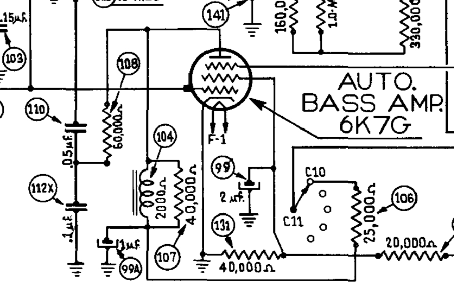
   

I couldn't find anything about that part (Part No. 32-7528) other than the DC resistance of 2000 ohms labeled on the schematic.

What inductance and current rating should I look for in a replacement? Any thoughts on if I should try to get it rewound or just replace it with a modern equivalent?
#32

In all honesty, my bass ctl is very slightly noticeable. First I thought it was nothing at all. Then I heard the change but it is very...light. (in 38-690).

People who do not drink, do not smoke, do not eat red meat will one day feel really stupid lying there and dying from nothing.
#33

Great job Nathan! It is nice to get sound after all of that work. I'm sure you will have a couple bugs to repair, then adjustments and alignment but the worst part is over  Icon_thumbup
#34

Thanks Keith! I agree - it's much less nerve wracking to work on a mostly working radio.

Interesting about the limited bass adjustment Mike. I did remove the audio choke and sure enough it is open.

It has wire leads so I took it apart to see if it was just broken where the wires connect. It wasn't - the break must be internal.

The good news is that I found the specs on Part No. 32-7528 in the 1942 Philco Parts Catalog.  Icon_thumbup

   
  • 65H
  • 2,250 ohm (approx the 2,000 labeled on the schematic)
  • 10mA rating
  • 2"H x 1 3/4"W x 1 5/8"D

It has 2 1/4" mounting holes.

What do you guys think of Hammond 155C as a replacement? The specs are:
  • 60H
  • 2,750 ohm
  • 8 mA rating

The current rating is lower (8mA vs 10mA) but the resistance is higher than the original Philco part (2750 ohm vs. 2250 ohm).
So does that mean the max design voltage should be 225V and so 225V / 2750 ohm = 8.18 mA = close enough?
#35

Mine is 38-690, no choke there in bass amp.

People who do not drink, do not smoke, do not eat red meat will one day feel really stupid lying there and dying from nothing.
#36

Right. I'll still need to find a replacement for my 37-690 though. Icon_smile
#37

Current wise it's pretty close but two things to consider. One plate current on 6K7 is 7ma @250v and the other is that there is a resistor across  it which limits the current. Think your be OK.

When my pals were reading comic books
I was down in the basement in my dad's
workshop. Perusing his Sam's Photofoacts
Vol 1-50 admiring the old set and trying to
figure out what all those squiggly meant.
Circa 1966
Now I think I've got!

Terry
#38

Thanks very much Terry!
#39

The Hammond 155C choke arrived much quicker than expected. I ordered from Arrow Electronics - which has 1-day shipping on everything! I expect it's a promotion and won't be that way forever, but it sure was convenient.

Audio Choke

The new choke was almost exactly the same height as the old one was wide. I derusted and repainted the shell after I realized I could reuse it. I removed the outer mounting bracket, rotated it 90 degrees, and it fit perfectly inside the old transformer case.

[Image: https://farm2.staticflickr.com/1854/4285...23d6_z.jpg]

[Image: https://farm2.staticflickr.com/1923/4393...5b66_z.jpg]

[Image: https://farm2.staticflickr.com/1957/4393...6fb7_z.jpg]

Main Chassis Derust

The other thing I've been doing with the 37-690X is removing the rust on the main chassis. Like the power/amp chassis, this one took several days of applying Evaporust Gel for a few hours - and resorting to naval jelly on the really stubborn spots. Finally I sealed it with Boeshield (that's why the chassis looks a bit wet in the 'after' pic below).

Before:
[Image: https://farm2.staticflickr.com/1875/4463...73de_c.jpg]

After:
(I forgot to take one before replacing the tubes)
[Image: https://farm2.staticflickr.com/1975/4487...296d_c.jpg]
#40

Yes, I'm still working on this beast. I've been regluing things on the cabinet and derusting yet more parts.

Today I fixed a few remaining issues and got to the alignment.

It took me a while to get the tuning mechanism back in the right order - and had to review the Philco Automatic Tuning service bulletin as well as the (inadequate) photos I had taken earlier when I disassembled everything. For the record here are the steps:

Step 0
[Image: https://farm2.staticflickr.com/1941/3020...fd04_z.jpg]

Step 1 - Control Screw Housing
[Image: https://farm2.staticflickr.com/1903/4442...106c_z.jpg]

Step 2 - Retaining Spring
[Image: https://farm2.staticflickr.com/1921/3127...4049_z.jpg]

Step 3 - Reflector Ring
[Image: https://farm2.staticflickr.com/1934/4509...1ccc_z.jpg]

Step 4 - Mask Assembly
[Image: https://farm2.staticflickr.com/1940/3020...ac2c_z.jpg] [Image: https://farm2.staticflickr.com/1927/4423...4296_z.jpg] [Image: https://farm2.staticflickr.com/1979/4514...5d43_z.jpg]

Step 5 - Spacing Ring
[Image: https://farm2.staticflickr.com/1909/4442...d767_z.jpg] [Image: https://farm2.staticflickr.com/1923/4442...bcf0_z.jpg]
[Image: https://farm2.staticflickr.com/1907/4509...d2dc_z.jpg]

Step 6 - Dial gaskets and Dial
[Image: https://farm2.staticflickr.com/1912/3020...4c7f_z.jpg]
[Image: https://farm2.staticflickr.com/1943/4514...4fff_z.jpg]
[Image: https://farm2.staticflickr.com/1923/4514...9c6b_z.jpg]

Step 7 - Station Tab Escutcheon Assembly
[Image: https://farm2.staticflickr.com/1902/4333...6f5b_z.jpg] [Image: https://farm2.staticflickr.com/1933/4509...4085_z.jpg]
[Image: https://farm2.staticflickr.com/1964/4333...1745_z.jpg]

Step 8 - Dial Screen Holder Assembly
[Image: https://farm2.staticflickr.com/1938/4442...2170_z.jpg]
[Image: https://farm2.staticflickr.com/1946/3127...606a_z.jpg]

Step 9 - Switch Contact (movable, audio shorting)
[Image: https://farm2.staticflickr.com/1920/4514...4cda_z.jpg]

Step 10 - Washer, fibre (audio switch, movable section)
IMPORTANT: goes on *after* the audio shorting switch.
[Image: https://farm2.staticflickr.com/1951/3127...61a9_z.jpg]

Step 11 - Handle
[Image: https://farm2.staticflickr.com/1964/4514...b891_z.jpg] [Image: https://farm2.staticflickr.com/1915/4423...9d1b_z.jpg]

Step 12 - Retaining Spring
[Image: https://farm2.staticflickr.com/1942/4423...b9a2_z.jpg]

Step 13 - Handle Cover
[Image: https://farm2.staticflickr.com/1909/4514...5ac0_z.jpg]
[Image: https://farm2.staticflickr.com/1912/3020...a7a1_z.jpg]

Done

[Image: https://farm2.staticflickr.com/1903/3020...37ed_z.jpg]
#41

...whew!... Icon_eek
Icon_clap
#42

Been through that several times, pretty recently.

People who do not drink, do not smoke, do not eat red meat will one day feel really stupid lying there and dying from nothing.


Users browsing this thread: 1 Guest(s)