Posts: 15,306
Threads: 531
Joined: Oct 2011
City: Jackson, NJ
Today I started rebuilding the tone control, and I noticed that there are two wires that came to the middle tone ctl position, not one.
I separated them, and then I realized that there was a capacitor between the 1st and the middle positions, but there were no cap between the 1st and the common at all. So the capacitance of the 1st position is the series value of the capacitor between the common and the middle and the one from the middle to the 1st.
Ok, one cap less.
Here it is:
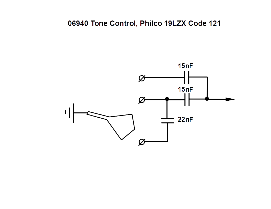
It is very much the same as 30-4043/4208/4220/4378/4056 parts. The values are close, theirs are 10nF/15nF/10nf wheres mine are 22nF/15nF/15nF. I wonder if I should just take the values from the book.
People who do not drink, do not smoke, do not eat red meat will one day feel really stupid lying there and dying from nothing.
(This post was last modified: 08-22-2020, 03:50 PM by morzh.)
Posts: 15,306
Threads: 531
Joined: Oct 2011
City: Jackson, NJ
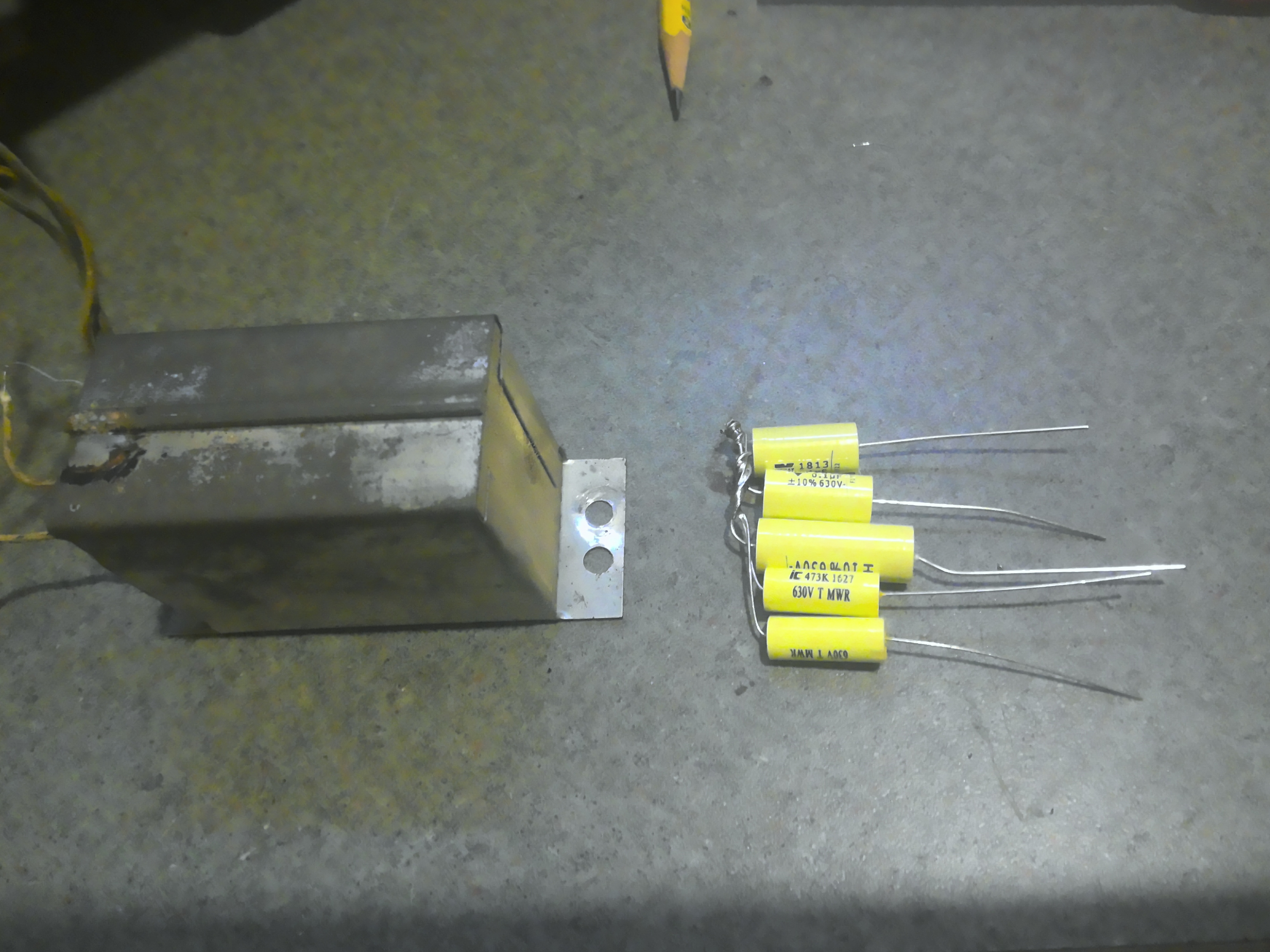
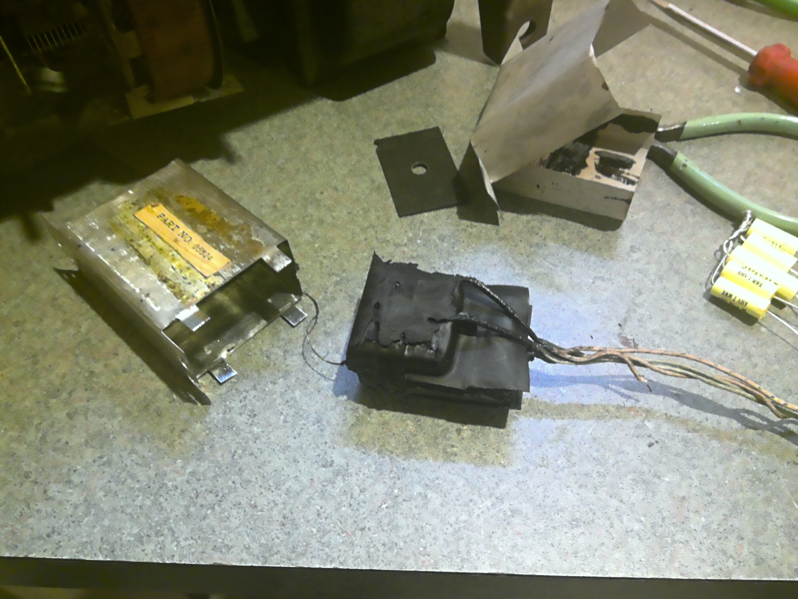
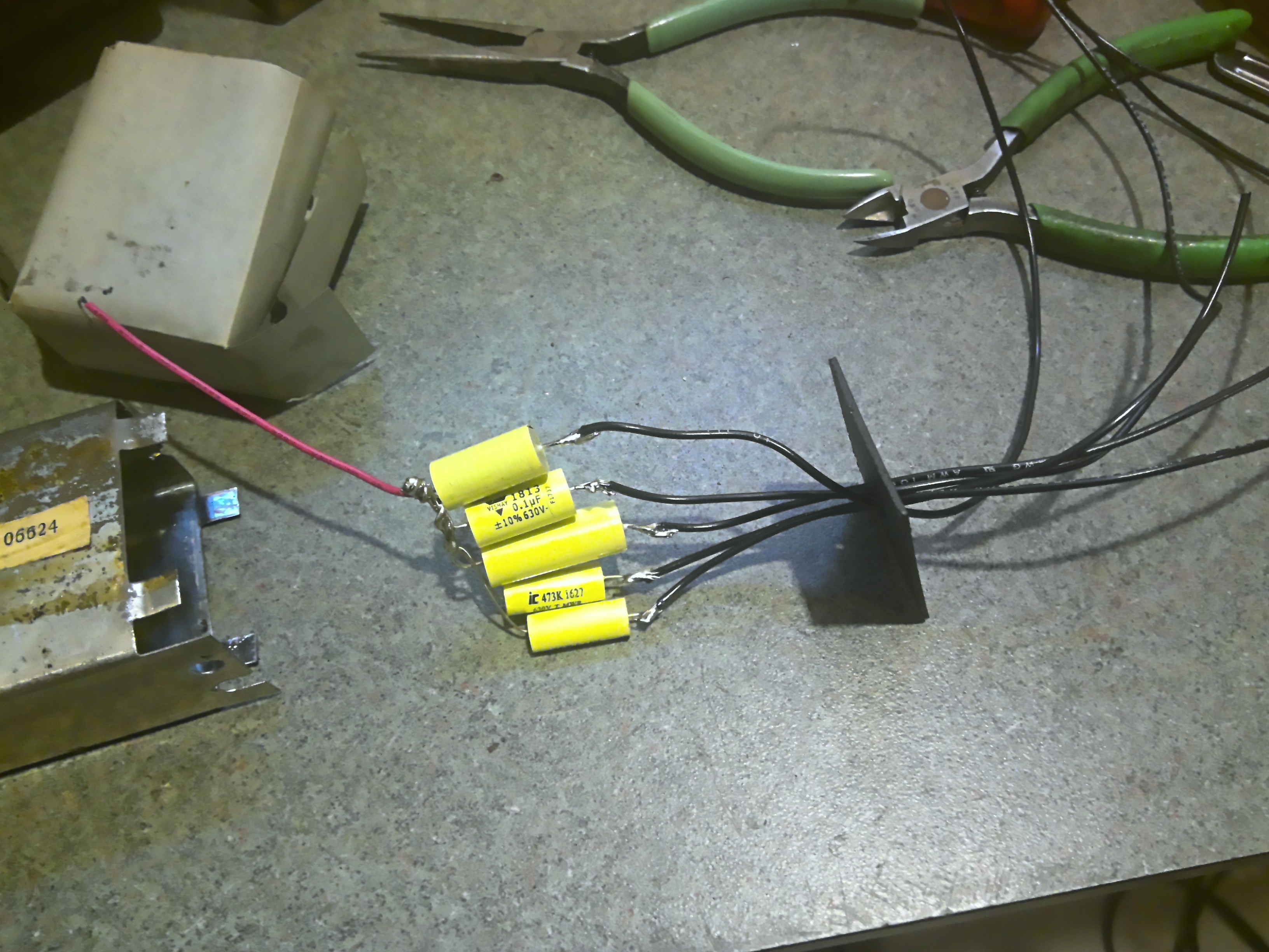
These are the three caps.
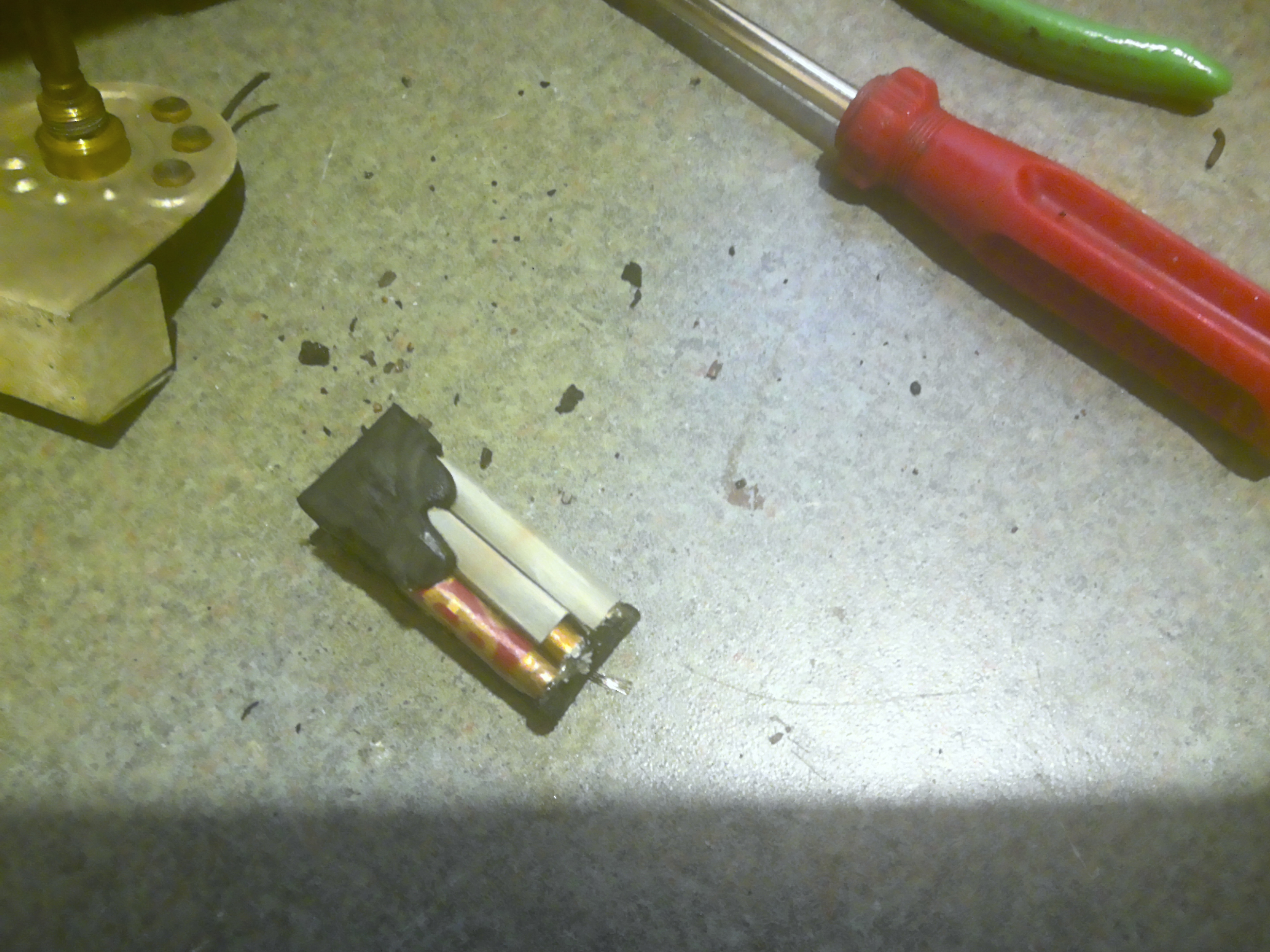
And the new ones are covered with a piece of fish paper and ready to pot.
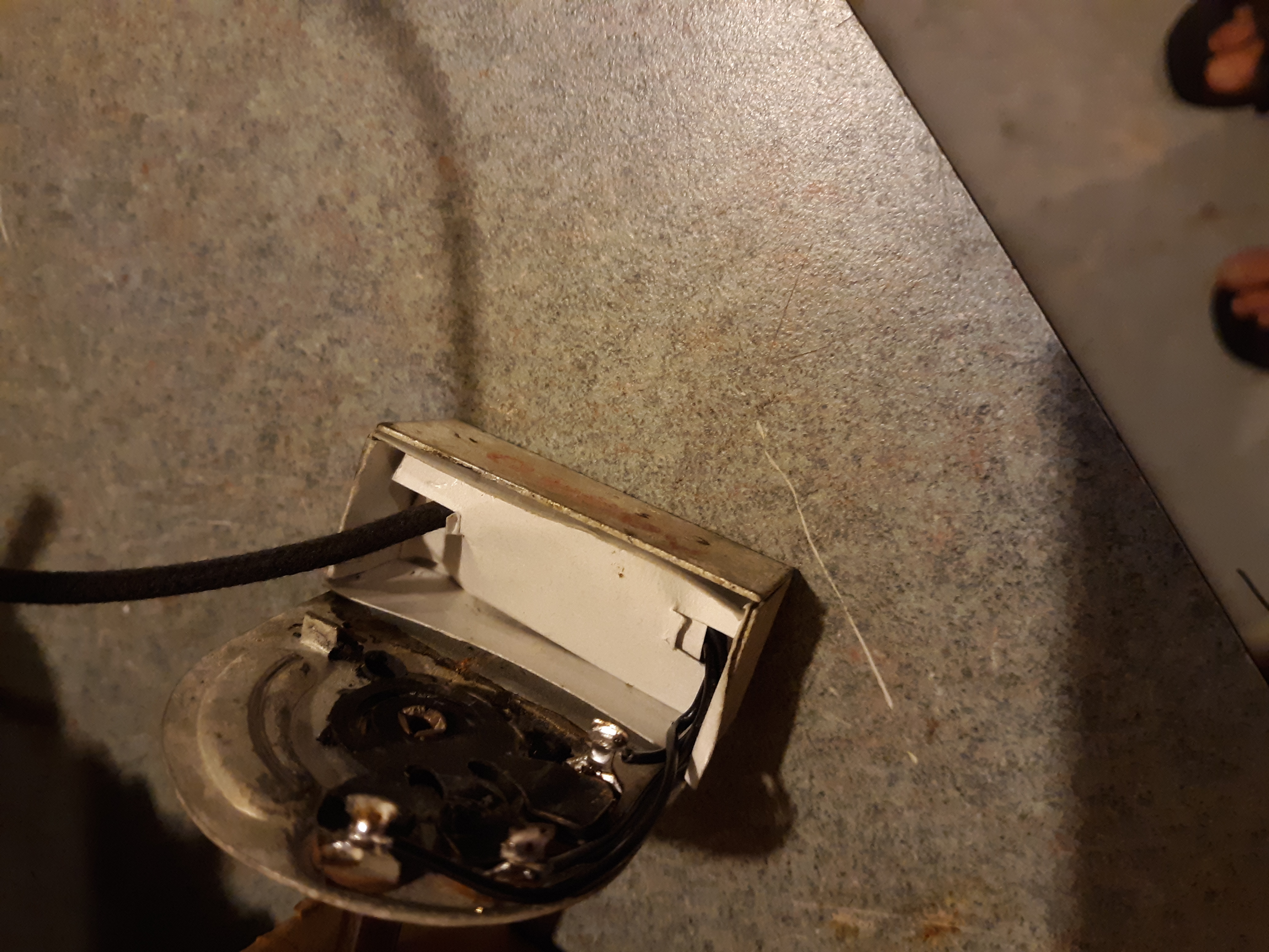
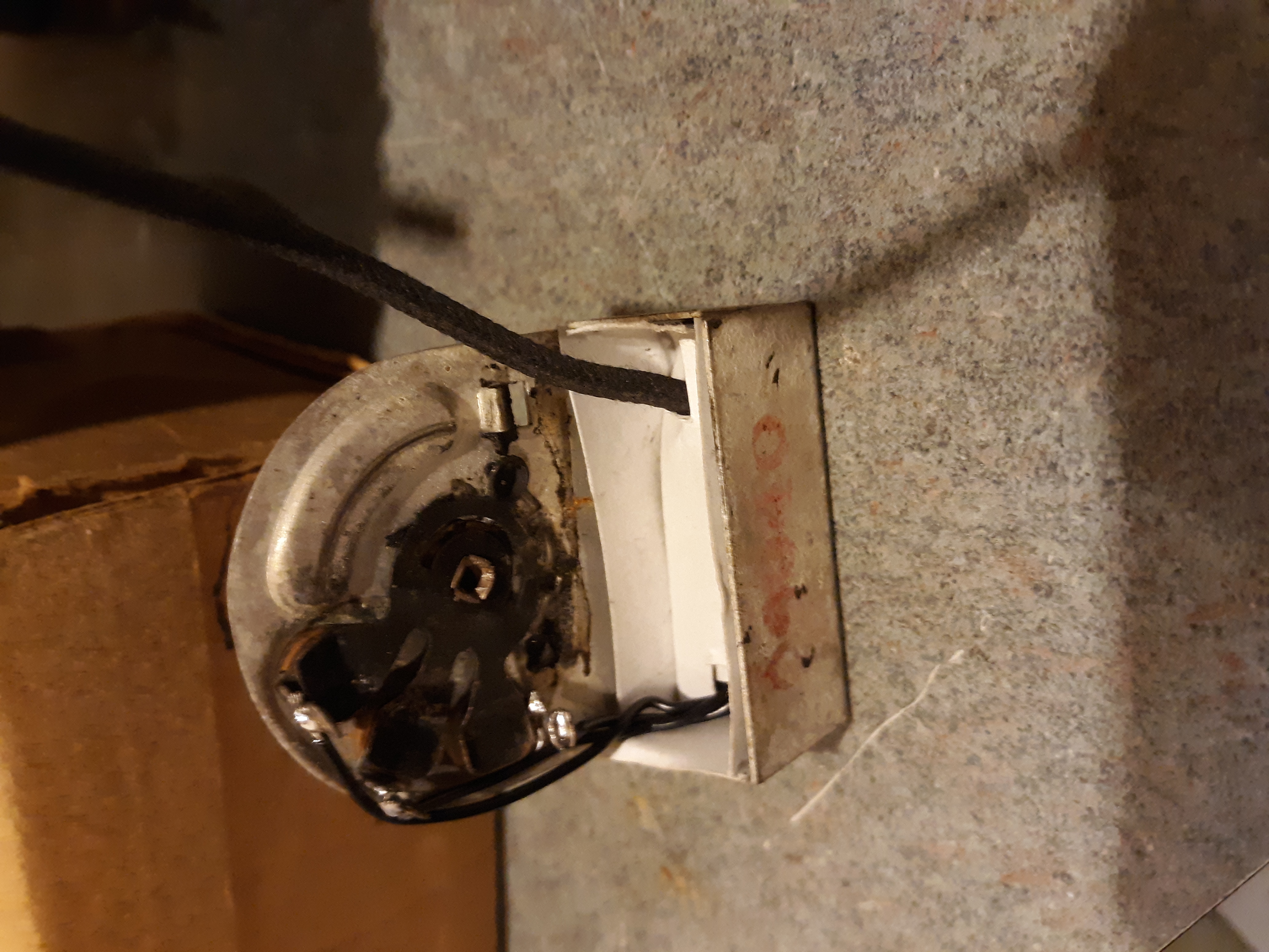
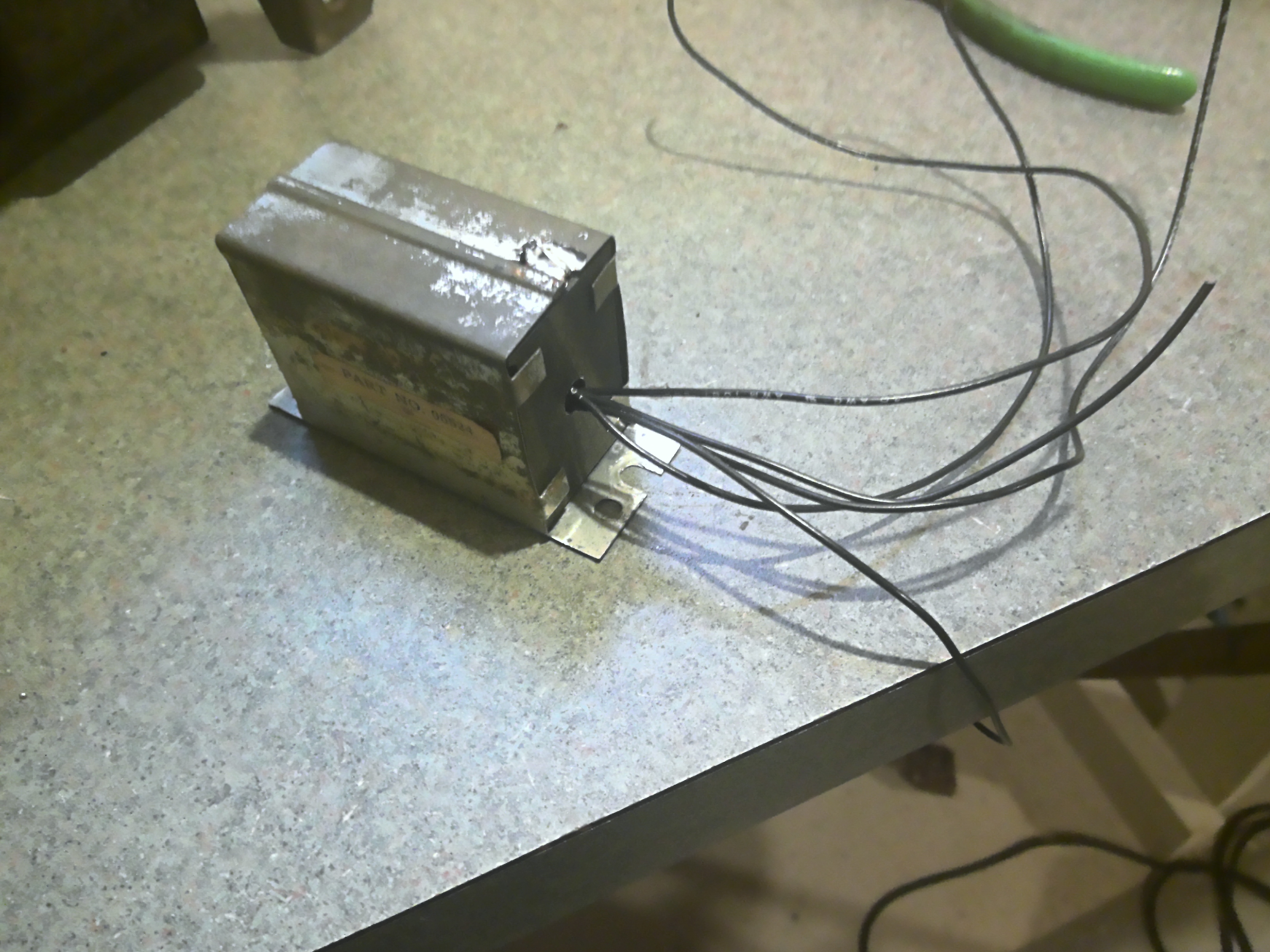
Potted

People who do not drink, do not smoke, do not eat red meat will one day feel really stupid lying there and dying from nothing.
Posts: 1,475
Threads: 69
Joined: Nov 2012
City: Kansas city, MO.
Under chassis restoration looking good Mike.  Did not have an answer for your tone control, but I have been following along with your restoration.
Posts: 15,306
Threads: 531
Joined: Oct 2011
City: Jackson, NJ
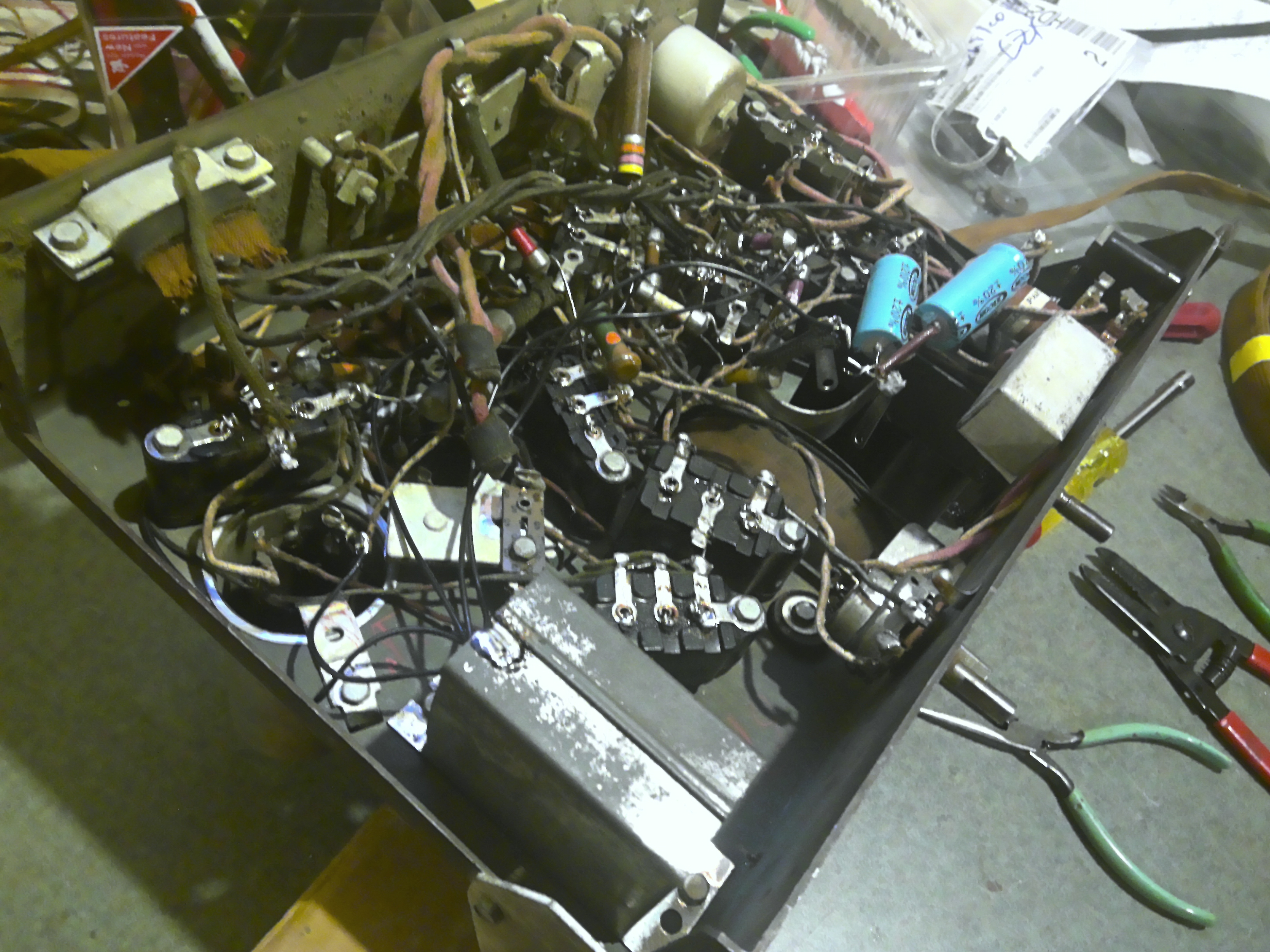
Trying to use the *2 rule for capacitor drift clearly proved inadequate for the #7 capacitopr filter block.
The values started from about 0.3uF whereas they should start from 0.05uF.
The highest, 0.7uF was supposed to be 0.25uF.
Anyhow, Ray's book has the block and the block retained the label so I know it was not anything else.
People who do not drink, do not smoke, do not eat red meat will one day feel really stupid lying there and dying from nothing.
Posts: 15,306
Threads: 531
Joined: Oct 2011
City: Jackson, NJ
The final part of the recap is electrolytics.
Since they are in the cardboard sleeves, they do not have to look good where they are glued, just be sturdy enough to withstand the bracket's pressure.
I eventually went with 22uF 250V : they are small enough to fin 3 of them in the can, and in series they make 7uF which is what I need.
These are 560mA ripple so are very good. To control distribution I put 2.2M resistors across each of three.
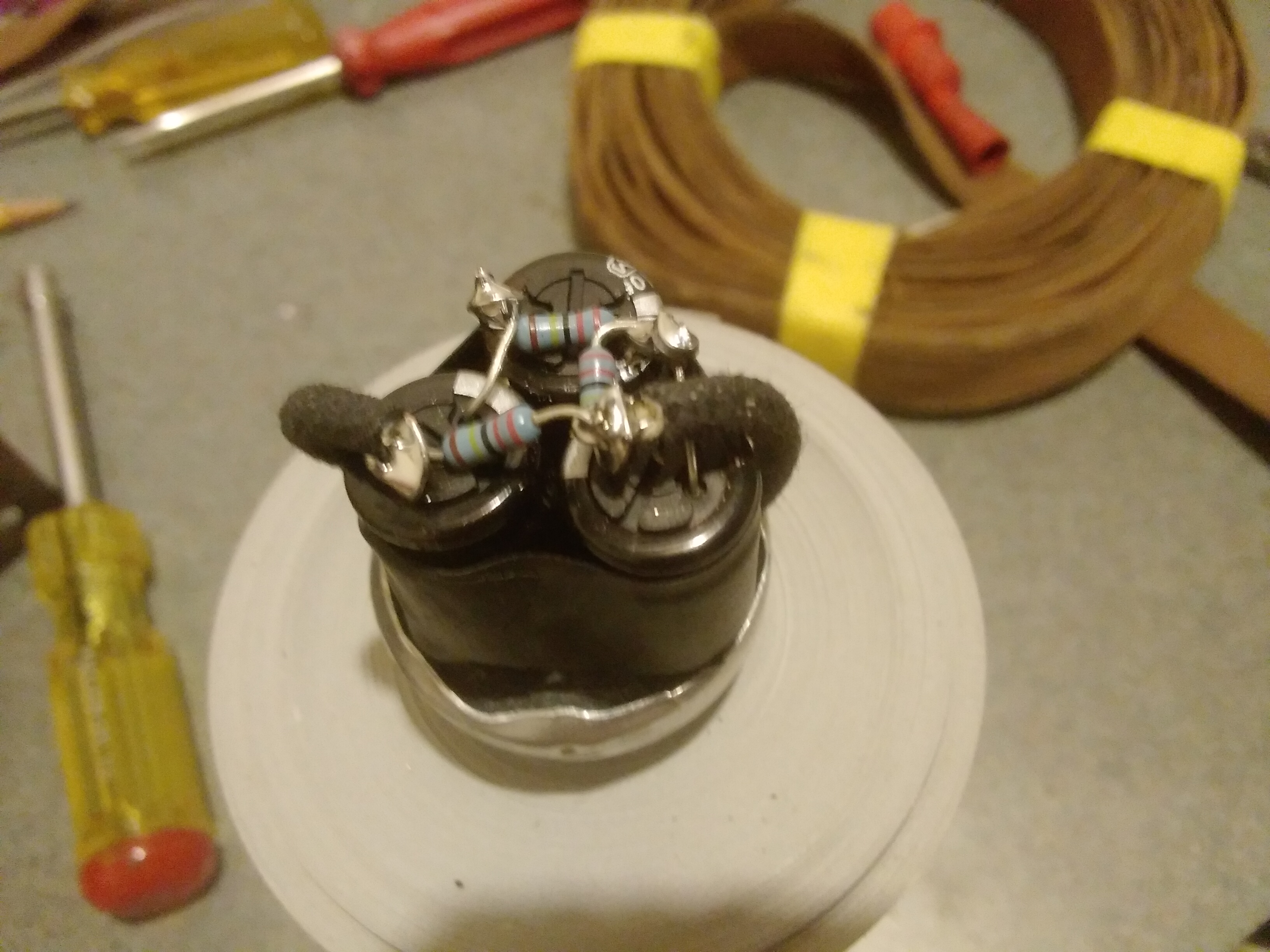
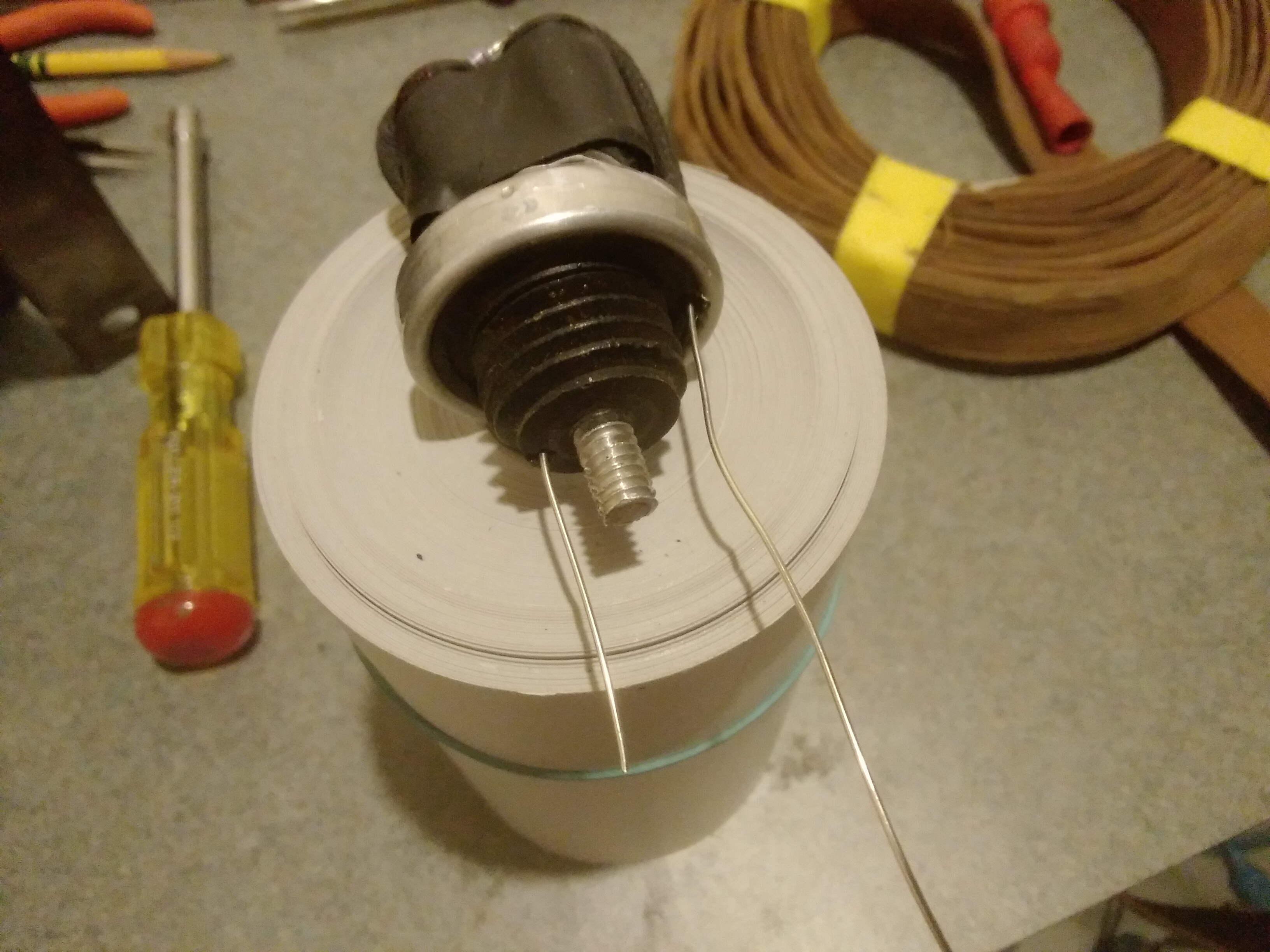
The second cap does not have to be as good with the ripple or to be 6uF, it can be a GP cap. I reused 22uF axial cap that was in the radio, it is a Xicon and thereby a major component brand, and being a single is easy to put inside.
I use ring terminals to both terminate the Positives, and also to connect the screw to the rest of the chassis. The Minusses will be connected to the inserts that go under the cardboard sleeves.
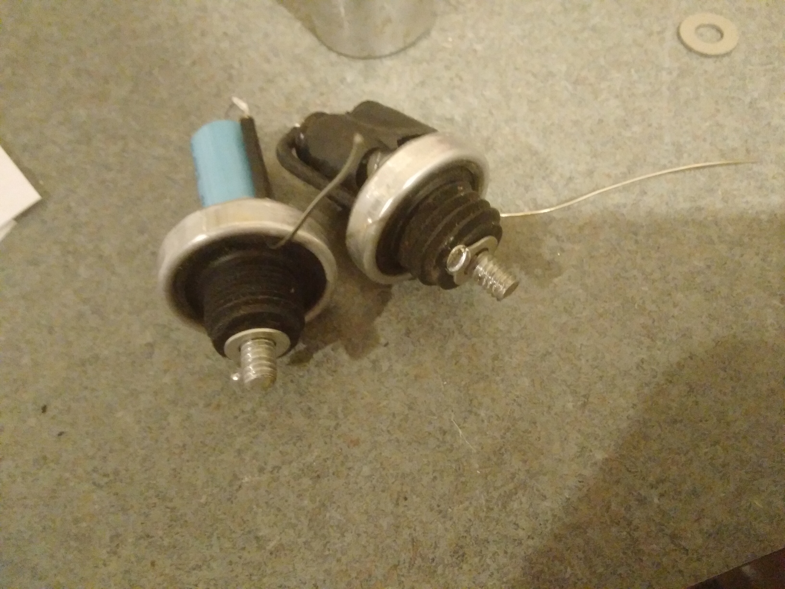
Ready to be glued.
People who do not drink, do not smoke, do not eat red meat will one day feel really stupid lying there and dying from nothing.
Posts: 3,105
Threads: 54
Joined: Apr 2011
City: Lexington, KY
Mike, why the three 22's with the resistors? I understand the theory behind the resistors, but it seems like a single 8 of good quality would have been sufficient.
John KK4ZLF
Lexington, KY
"illegitimis non carborundum"
Posts: 15,306
Threads: 531
Joined: Oct 2011
City: Jackson, NJ
I know.
1. I have to put in that single 8. It is a pretty expensive Solen. $6.70 apiece. I got'em. But.....somehow this radio didn't scream at me about an expensive 8uF Solen 
2. I got plenty of inexpensive (compared to Solens) good high ripple (560mA) Panasonic aluminum cans. They are $0.70 apiece in qty 10, I got 20.
3. The voltage in the outlet being higher today, every extra uF matters. 7uF is better than 8.
So....honestly, I do not think Solen beats Panasonic here. I might even get away with it without resistors, and usually when using 450V caps I do, but these being 250V, I decided to put the resistors in.
A well-picked electrolytic cap is almost as good as the film. A 560mA ones are going to be very comfy working here.
People who do not drink, do not smoke, do not eat red meat will one day feel really stupid lying there and dying from nothing.
Posts: 3,105
Threads: 54
Joined: Apr 2011
City: Lexington, KY
OK, that's a little more $$$ saved for an 'Old Speckled Hen' 
I wasn't really considering a Solen for that, especially since you used electrolytics, but a good ole single 8uf electrolytic. I've got some nice Sprague 8uf's that I would have probably used if I wasn't going the Solen route. But the three 22's with balancing resistors do make for more interesting reading.

John KK4ZLF
Lexington, KY
"illegitimis non carborundum"
Posts: 15,306
Threads: 531
Joined: Oct 2011
City: Jackson, NJ
John
I might consider this if:
1. I could find a single 8uF (8.2uF) 450V/500V cap that is not a Solen and with decent ripple rating. Here's Mouser search for it:
(8 - 8.4uF 450V - 540V)
https://www.mouser.com/Passive-Component...7oZ1ypax18
All the caps have about 88mA ripple. The one below is the only one that has 110mA at 120Hz:
https://www.mouser.com/ProductDetail/Uni...plWMHVU%3D
But even that.....
The ones I have have 560mA which is the same rating the resulting cap will have after the serializing. This gives me some peace of mind.
And in this day and age, peace of mind is everything 
PS. I do realize that with very little use each radio is seeing, the chance of the cap with even inadequate ripple rating being overworked is slim.....but, that is me. The EE in me is the enemy of good enough 
People who do not drink, do not smoke, do not eat red meat will one day feel really stupid lying there and dying from nothing.
(This post was last modified: 08-26-2020, 08:53 AM by morzh.)
Posts: 3,105
Threads: 54
Joined: Apr 2011
City: Lexington, KY
Mike, I wonder what the ripple rating was on that cap when fresh from the Philco factory floor 
I tend to be concerned about specs when replacing caps in more modern equipment, but these old radios don't concern me too much, except for Solens for their long life. But who am I kidding, almost everything I buy today comes with a (my) life-time warranty 
John KK4ZLF
Lexington, KY
"illegitimis non carborundum"
Posts: 15,306
Threads: 531
Joined: Oct 2011
City: Jackson, NJ
John
ripple rating is very much corelates with ESR (this will dictate the heat losses) and the size/temperature rating (this will dictate the heat transfer frm the cap to the ambient, and the resistance to heat damage). The old caps were large, so the cooling was not an issue.
I simply do not know their ESR or Ripple ratings as they were never published, or if they were - they are nowhere to be found.
But...them drying up withing 10 years or under (the repairs were often made in late 30-s - early 40s to replace the electrolytics) tells me that it was either the bad sealing and therefore evaporation of the liquid, or the same exacerbated by heating of the cap that would speed up the evaporation and drying up.
However I often find the same caps (like these two I just gutted) that are not dry and exhibit the capacitance in excess of the specified originally, which tells me they did not heat up much and maybe simple developed leakage. Which might be the result of not being subjected to high ripple.
So maybe their ripple rating was not that good after all, and it was just the question of the type of the circuitry they were working for: how much consumption, and therefore ripple current the cap experienced.
But it is all guesses by now: I doubt anyone ever did the measurements, or if someone did, that the records were kept.
Yes, even for me it is probably lifetime 
Hey.....there's that silver lining! 
People who do not drink, do not smoke, do not eat red meat will one day feel really stupid lying there and dying from nothing.
Posts: 15,306
Threads: 531
Joined: Oct 2011
City: Jackson, NJ
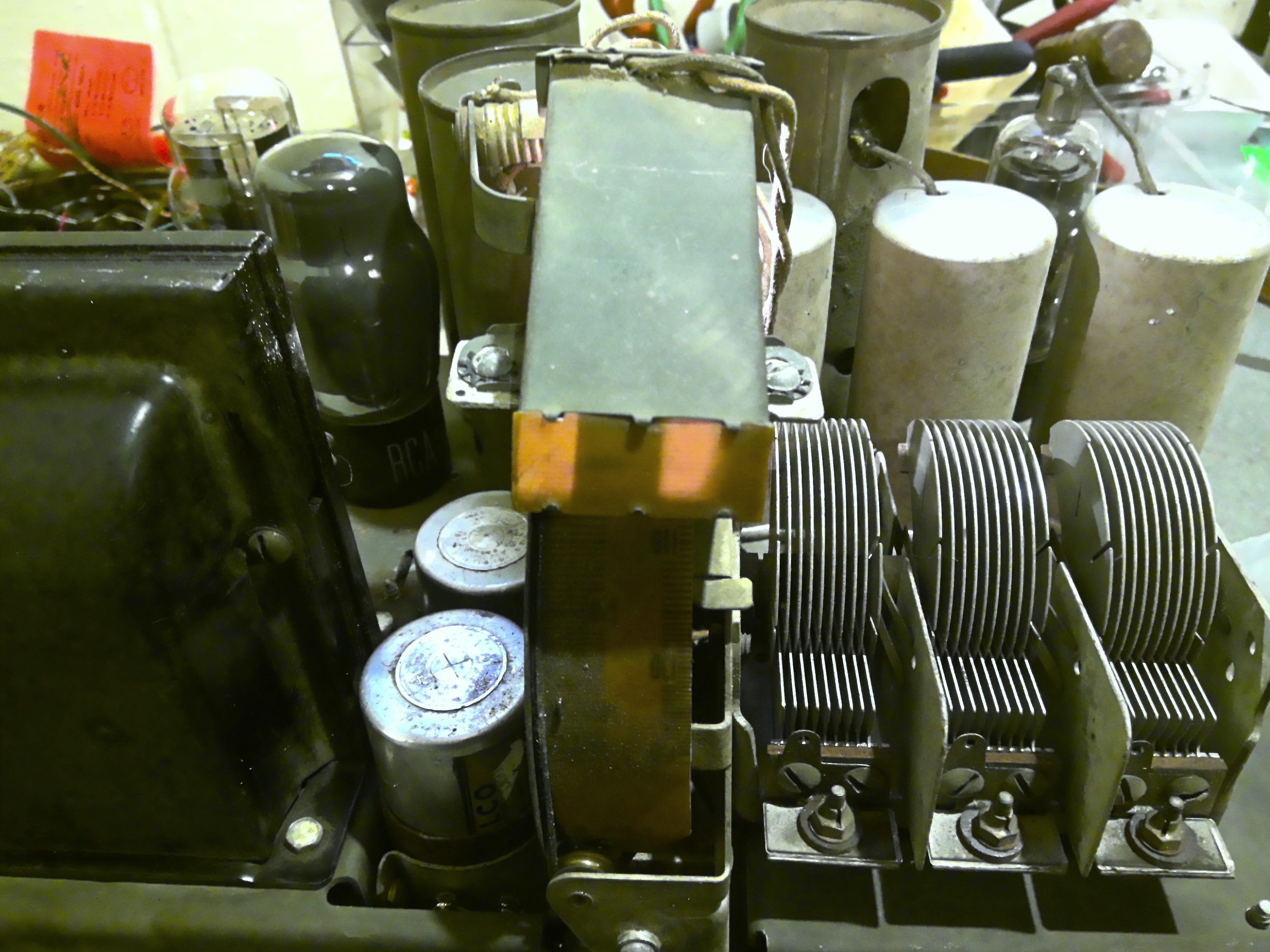
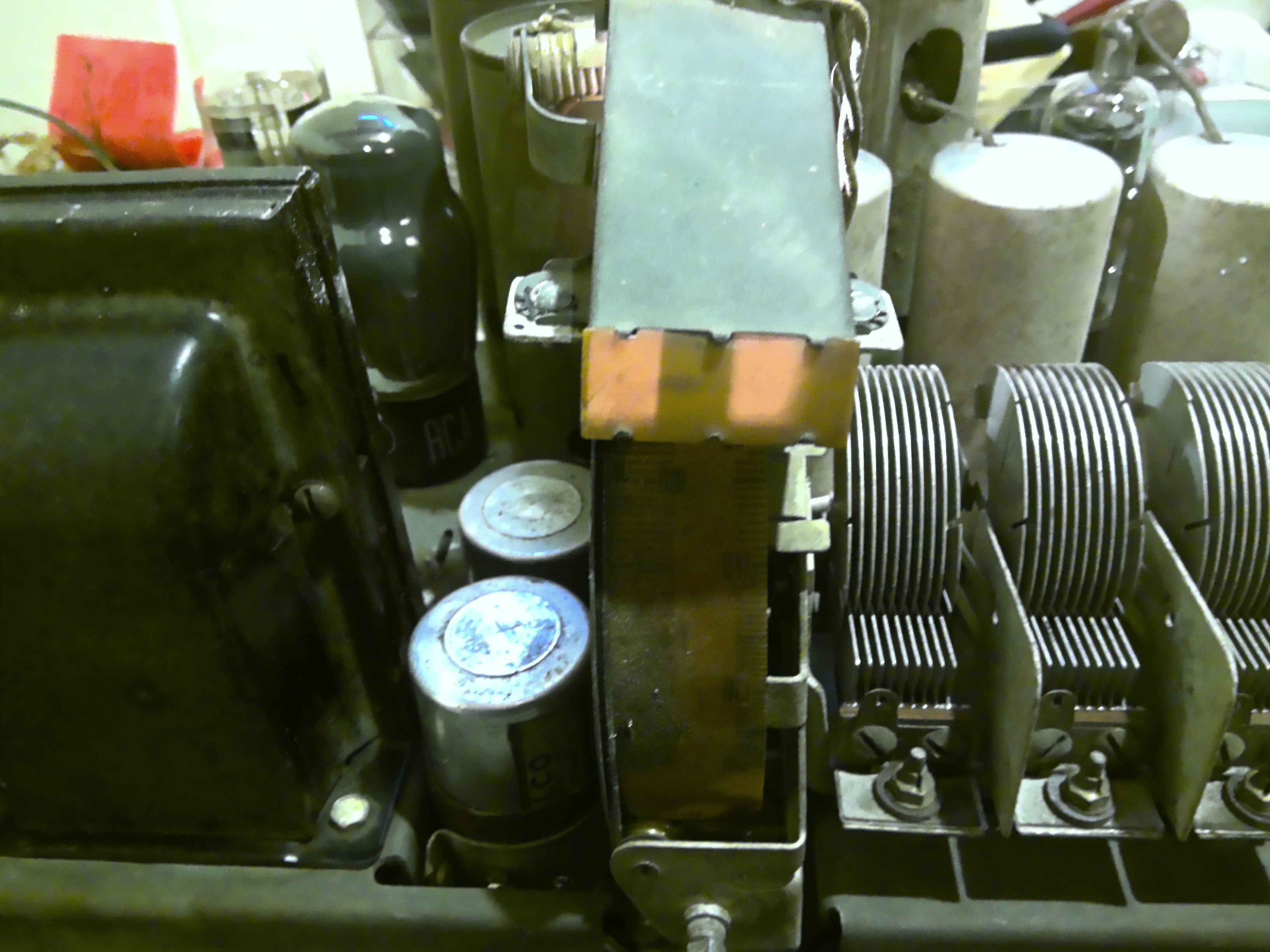
I re-installed the caps and soldered the minusses.
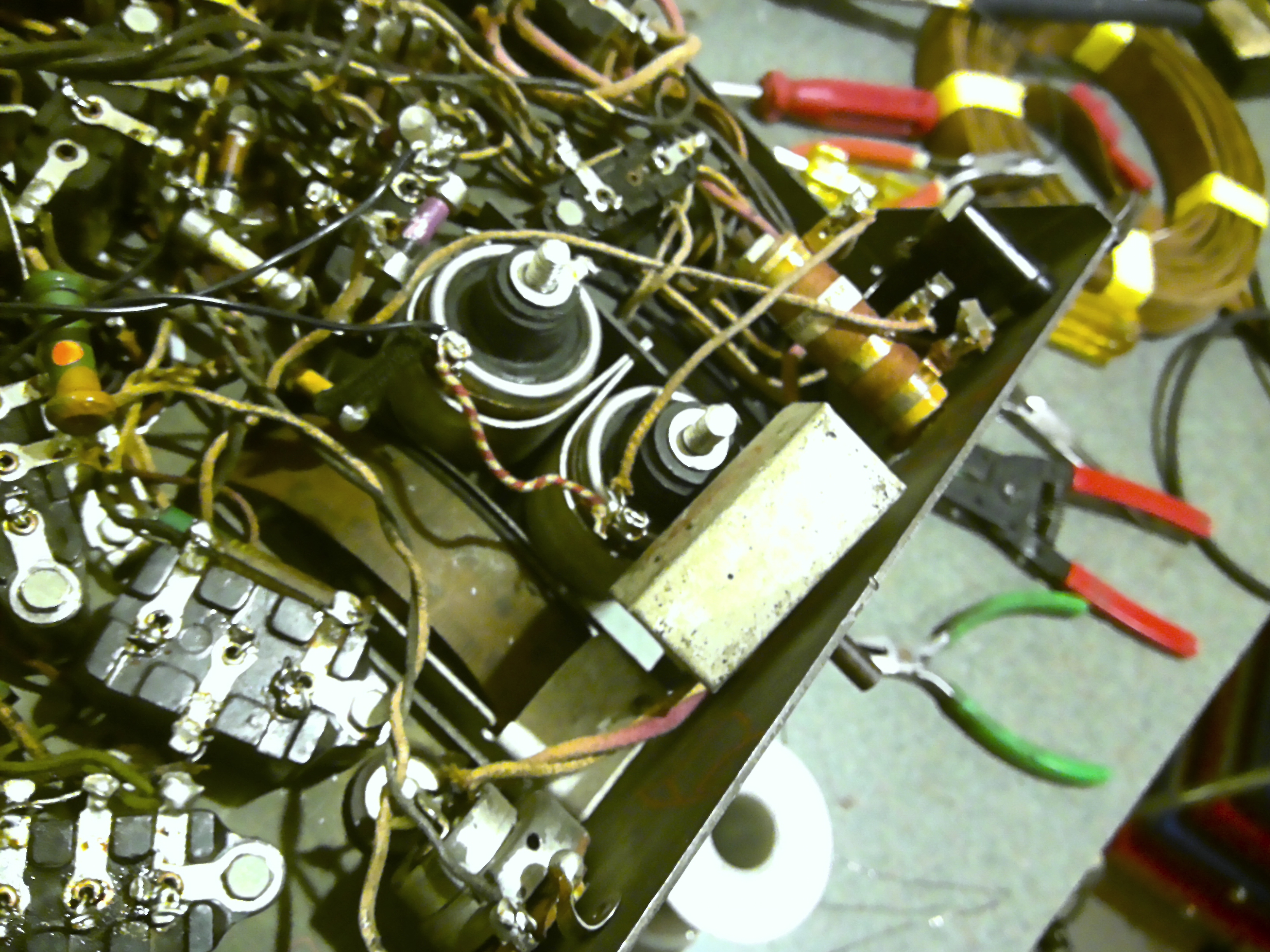
Gee.
The front of the radio is really busy.
I needed the caps out to take out the tone control.
Now with the tone control in place I could not re-insert the caps.
For those who will be doing the same:
You need the tone control in but loose.
Then reinstall the cap holding clamp, the one closest to the front (the other does not have to be removed in the first place). Put it from the top of the chassis (meaning, the chassis bottom facing up, you go from underneath). Then when you get the tabs in the slots, insert the holding pin. Then the screw and the nut. Then you could tighten the tone control back.
Now you could put the caps back.
The front cap's plus is really close to the tone control case, so I rotated the tone control, achieving the gap between the cap's center contact and the tone ctl case that is safe.
It was tiresome.
Will solder the rest tomorrow.
People who do not drink, do not smoke, do not eat red meat will one day feel really stupid lying there and dying from nothing.
Posts: 15,306
Threads: 531
Joined: Oct 2011
City: Jackson, NJ
Recap done.
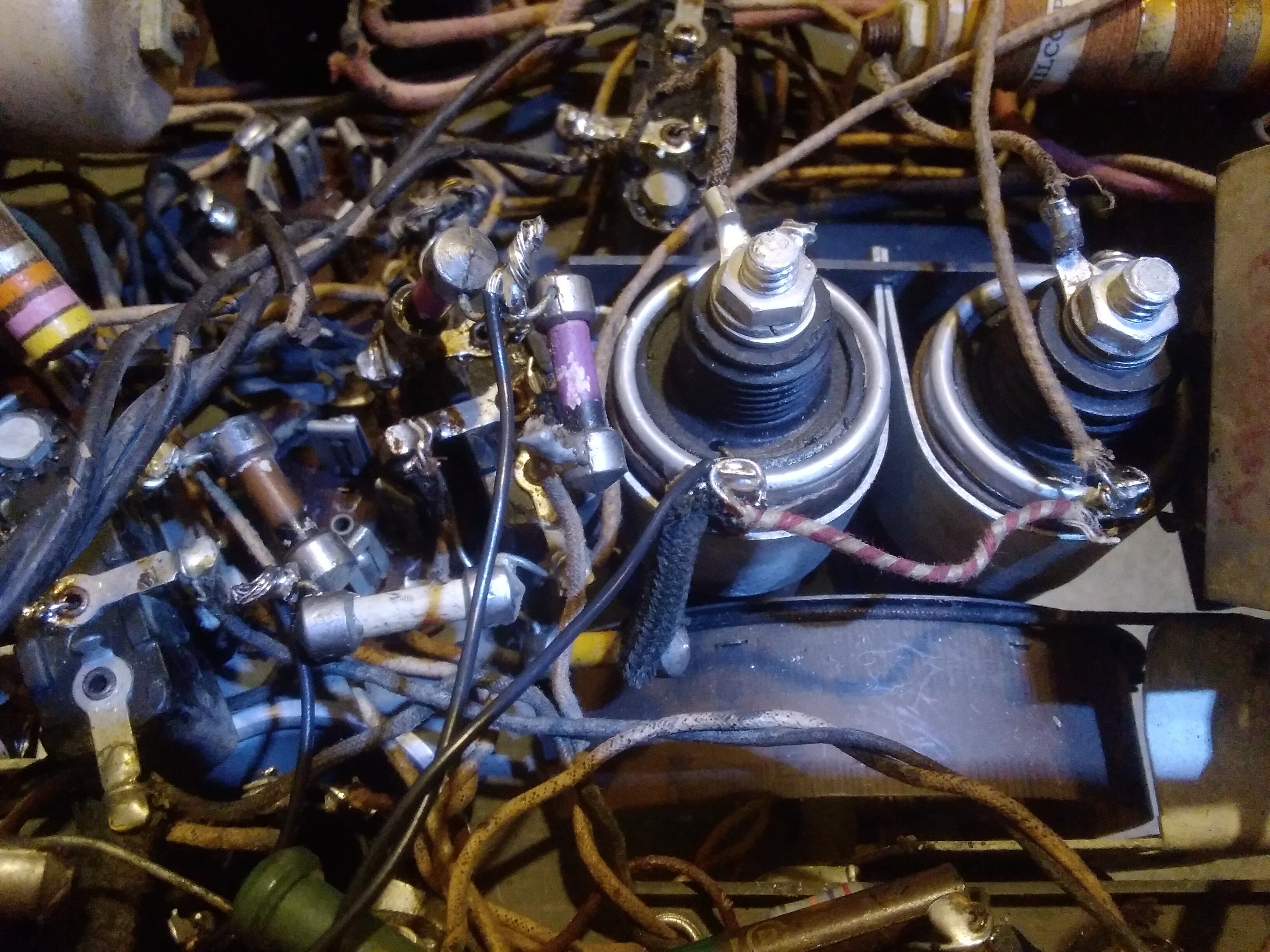
Decided to check the RF coils, noticed that the 2nd detector's tube cathode and its load, 2x70kOhms resistors, were not connected to the B+ while being connected to the rest of the circuitry.
I wonder how it worked before (it did, I heard it myself). Maybe it was, maybe I broke it off....but I always leave stubs.
Anywho, tomorrow I need to open up the speaker, inspect it, change the cord and totally broken AC plug.
Mulling the possibility of the flat cord change....but might leave it.
The outer plastic jacket is falling off, but underneath is another layer of insulation. Not sure ...it is not touching anything. Or I might snip the pieces and connect new wire under chassis only.....I will probably align it before I go to it, provided it even works, which I hope it will.
People who do not drink, do not smoke, do not eat red meat will one day feel really stupid lying there and dying from nothing.
Posts: 15,306
Threads: 531
Joined: Oct 2011
City: Jackson, NJ
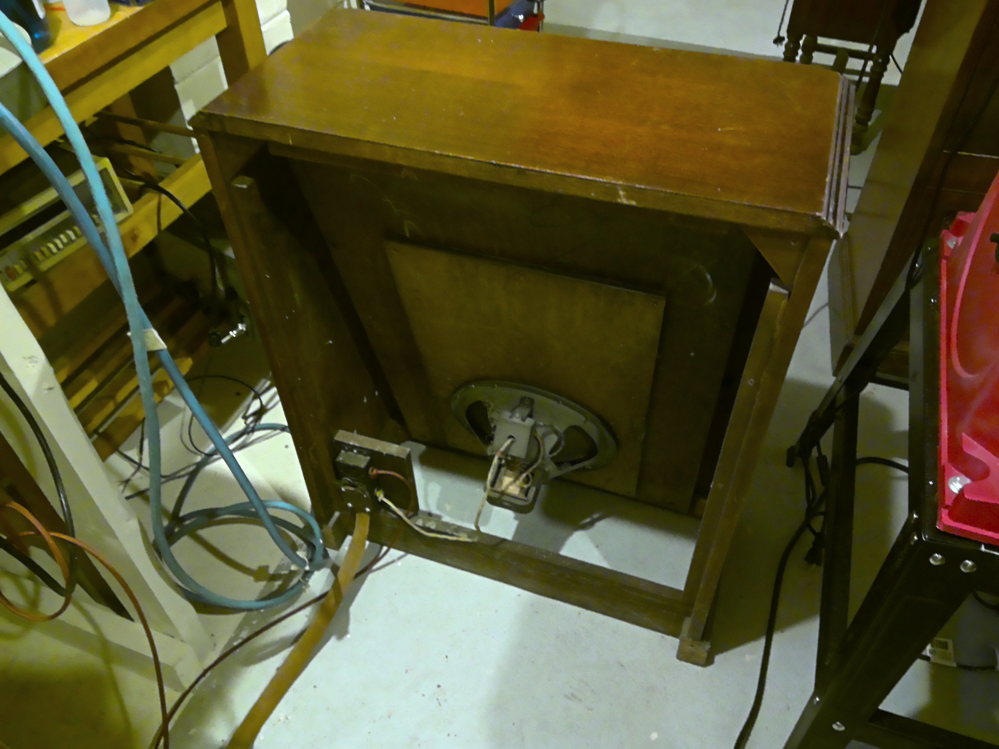
Today I opened up the speaker cabinet to change the power cord and inspect the rest.
Judging by the back of the cone and the condition of the cloth (intact) I figured the cone should be pristine.
I quickly measured the electricals, and found the output transformer and the field coil to be in good health.
I changed the power cord which was on the stiff side and started showing fraying of the cloth, plus the plug was broken beyond repair, so I changed it too.
Then came the tube check. All tubes test like new except the 36 which was testing OK, but not at or above the value shown in the Hickok table.
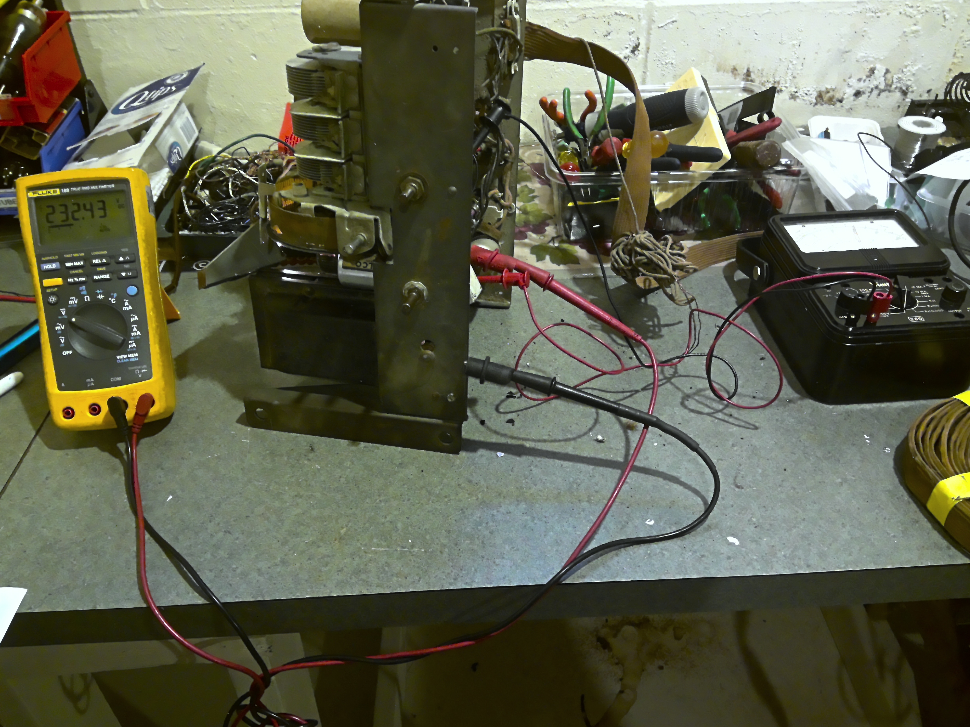
Then I plugged everything in except the rectifier, checked the filament voltage and the High Voltage, and put the rectifier in.
The voltage rose steady, then I heard some hum, and then I tuned into the local station and the reception was exceptional, as well as the sound that came out of that thing. BTW the tone Control works as it should and is very nice.
I thought of lubing the volume pot but it has zero scratching.
The Shadowgraph works too, though It does not spread all the way, but the reaction is pronounced, so I will not be trying to improve upon it.
Now the alignment.
People who do not drink, do not smoke, do not eat red meat will one day feel really stupid lying there and dying from nothing.
Posts: 4,335
Threads: 407
Joined: Jun 2011
City: Boston
State, Province, Country: Massachusetts
Nice to see that it turned out well!
Paul
Tubetalk1
Users browsing this thread: 2 Guest(s)
|


