Philco 600 schematic (different versions?)
Posts: 9
Threads: 3
Joined: Sep 2020
City: Valentine
State, Province, Country: Nebraska
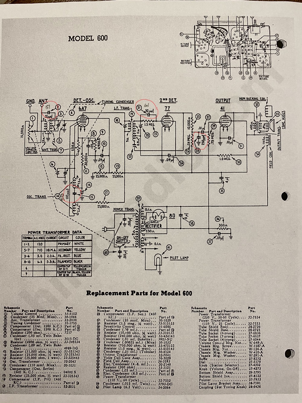
Hello guys, going through my schematic I'm finding that everything matches except for the mica's. I've read in other posts and watched videos of other repairs and most people leave the mica's alone. After testing them they are all out of tolerance, will probably replace them with the values that are in the radio rather than whats shown on the schematic. Just curious if anyone knows of a design change or something that might explain the discrepancy or have any other suggestions?

Posts: 833
Threads: 36
Joined: Feb 2015
City: Roseville, MN
I think it's best if you stick with the values in the schematic, especially in the oscillator and 6A7 circuit.
Posts: 7,212
Threads: 266
Joined: Dec 2009
City: Roslyn Pa
How do you know what the value of a given part is? Are you reading the color code or marking on the part? Or are you using a capacitance meter to read it? Just reading it with a meter may just indicate drift not necessarily a change from the factory. It's not unheard of for a set to have service notes from the factory depicting changes. Agree with Rod go with stated values on the schematic if there are issues they can be sorted as it comes together.
The only one that I see that is fairly different from the original is the 510 mmfd cap in the osc. It's controlling the feedback for the oscillator. All the other seem to be pretty negligible.
I would very interested to read the resistances of the windings on the ant, field, osc coils, and the output transformer. Some of which look like they have gnawed on.
GL
When my pals were reading comic books
I was down in the basement in my dad's
workshop. Perusing his Sam's Photofoacts
Vol 1-50 admiring the old set and trying to
figure out what all those squiggly meant.
Circa 1966
Now I think I've got!
Terry
(This post was last modified: 10-11-2020, 09:55 AM by Radioroslyn.)
Posts: 15,304
Threads: 532
Joined: Oct 2011
City: Jackson, NJ
How did you measure the values? In or out of circuit?
Is your meter capable of accurate wub-100pF measurements?
People who do not drink, do not smoke, do not eat red meat will one day feel really stupid lying there and dying from nothing.
Posts: 9
Threads: 3
Joined: Sep 2020
City: Valentine
State, Province, Country: Nebraska
I have a decent digital mm that measures to nf and a Heathkit C-3 that is fairly accurate. Maybe I was reading the color codes wrong, so the mica in the oscillator circuit in my radio is the Aerovox with the 3 dots, Blue Brown and Yellow which would be 610uuf or 610pf or .610nf correct. The Heathkit measured the mica at 140uuf out of circuit. I never would have went down this path until I noticed the color codes not matching values on the schematic. I see I wrote the wrong number on schematic earlier, should of been 610.
Posts: 15,304
Threads: 532
Joined: Oct 2011
City: Jackson, NJ
I would assume they are OK (hopefully you haven't damage them by soldering) and proceed with the rest.
Good rule is, do not touch micas unless you have a good probable cause to do so.
I am yet to replace one single mica in my radios.
People who do not drink, do not smoke, do not eat red meat will one day feel really stupid lying there and dying from nothing.
Posts: 9
Threads: 3
Joined: Sep 2020
City: Valentine
State, Province, Country: Nebraska
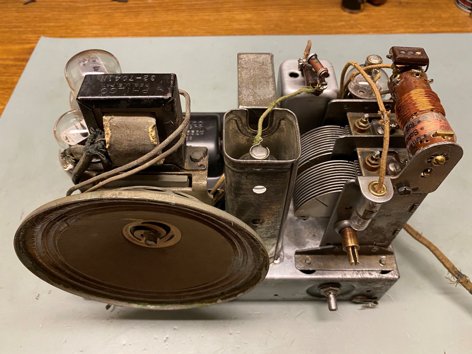
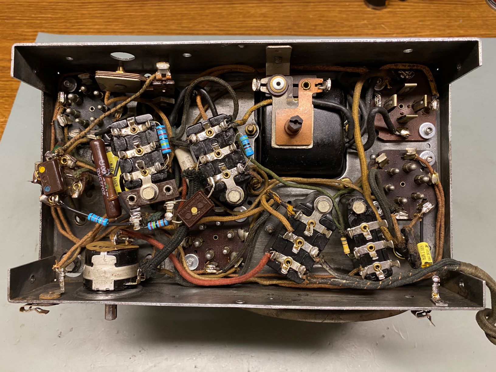
A little update on the Philco 600, I left the mica caps alone after reading what Morzh said "I am yet to replace one single mica in my radios." Thanks for the advice.
As you can see in the photo's it's a little cleaner, had to rewind the antenna coil it was chewed up really bad. Recapped and replaced all but 3 of the resistors. I replaced all the tubes except the 6A7, the 77 was missing, 41 had something rattling in the base and the 80 was cracked.
The radio works and seemed to align OK but when tuned to a strong radio station you can't turn up the volume or the radio makes an ungodly noise. The sensitivity control helps but at times you can't back it off far enough. Any ideas as to what might going on? I don't have an external antenna so just using a short piece of wire.
I am also looking for the tuning knob and pointer


Posts: 15,304
Threads: 532
Joined: Oct 2011
City: Jackson, NJ
The second backelite block from the left, top rivet - there was something in it.....?
People who do not drink, do not smoke, do not eat red meat will one day feel really stupid lying there and dying from nothing.
(This post was last modified: 11-03-2020, 07:53 PM by morzh.)
Posts: 9
Threads: 3
Joined: Sep 2020
City: Valentine
State, Province, Country: Nebraska
There was.... good find, there should be two .05uf inside
Posts: 9
Threads: 3
Joined: Sep 2020
City: Valentine
State, Province, Country: Nebraska
Was excited to fix my mistake and see how the radio would work so stayed up a little later last night. Got it back together and it sounds so much better, thanks again for spotting that.
I must have been really distracted that day
Posts: 102
Threads: 14
Joined: Jul 2017
City: Bakersfield, CA
I just found a 600 like yours which the seller was non-operating. After a little work it works but not a lot of volume yet and I still have to align it, etc.
My question is: did you find a black, stiff paper heat liner sitting on the bottom cover? It is shaped and cut to fit it exactly. If so, any guess of what it's made of? Any help would be great.
Thanks for taking the time to reply.
Posts: 7,212
Threads: 266
Joined: Dec 2009
City: Roslyn Pa
It's almost like a thin version of tar paper.
When my pals were reading comic books
I was down in the basement in my dad's
workshop. Perusing his Sam's Photofoacts
Vol 1-50 admiring the old set and trying to
figure out what all those squiggly meant.
Circa 1966
Now I think I've got!
Terry
Posts: 102
Threads: 14
Joined: Jul 2017
City: Bakersfield, CA
Yes, that's correct. I was hoping it is not some sort of asbestos sheet. I plan to spray it with a flat black, high-heat automotive spray paint, in case it is, and seal it.
Sound good?
Posts: 102
Threads: 14
Joined: Jul 2017
City: Bakersfield, CA
I went ahead and sprayed it. It worked fine and the radio is back together. It plays pretty well for something I was told wouldn't work.
https://www.facebook.com/1110071619/vide...4680510995
Posts: 1,824
Threads: 114
Joined: Jul 2014
City: Sneedville, TN
Sounds great and looks great ! Congratulations !
Users browsing this thread: 1 Guest(s)
|


