Posts: 337
Threads: 13
Joined: Apr 2019
City: Greenwood
State, Province, Country: Delaware
Well Mike; no.58 started crackling and sparking smoke and flames after 3 hrs, so I did what you said and subbed with 10w 3.5K.
Now it runs perfectly. This thing picks up a lot of stations, even on a 20' pc. of wire!
Oh yeah, I found the source of big RFI in the house; it was the Keurig coffee maker!! I now keep it unplugged until I need it. There is still other interference, but nothing like that little jamming machine!!
But, back to the action;
Rebuilt Tone Control
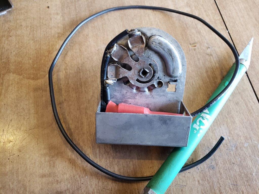
I removed the Tuning Capacitor, and installed 2 pc. Grommets that I 3-D printed at work. here are the glued-in upper halves.
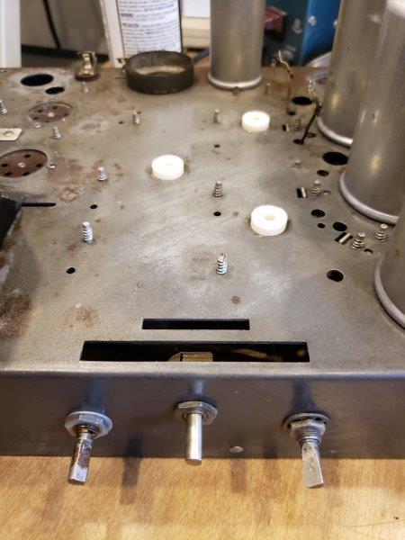
Here are the grommet upper and lower halves before installation. Still using the little metal tube like original.
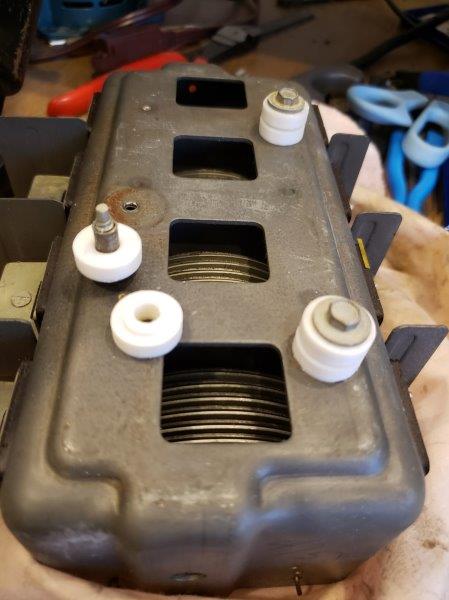
Tuning Cap went into the dishwasher after removing the mica caps; I took note of the turns before removing
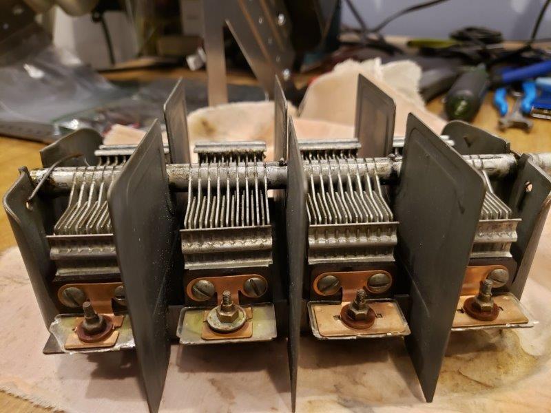
Long story short, all the bakelites are rebuilt, resisters replaced, electrolytics, bypass, and filter caps rebuilt. This picture is before the BC resistor flamed out and I installed the aforementioned 10w unit.
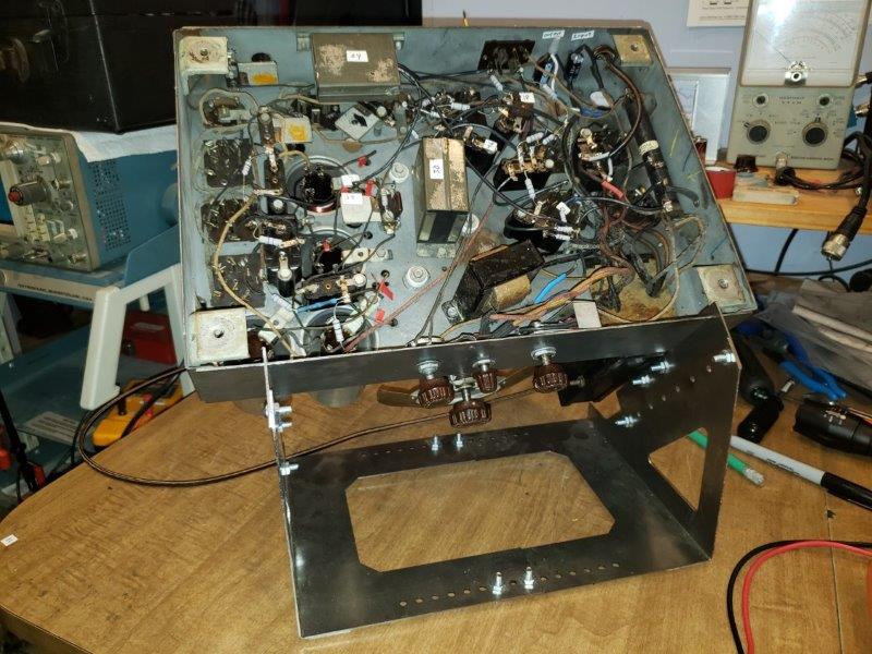
I will put in a wanted ad for a missing Sprague Electrolytic unit (for show only), and somebody owes me a tube shield so I can align this rascal (not putting any heat on you, bob 
So thats it for time being.
Simon
Posts: 337
Threads: 13
Joined: Apr 2019
City: Greenwood
State, Province, Country: Delaware
Comparing ye old signal generator with Kenwood 590s, we see 172.5 kc on Band A
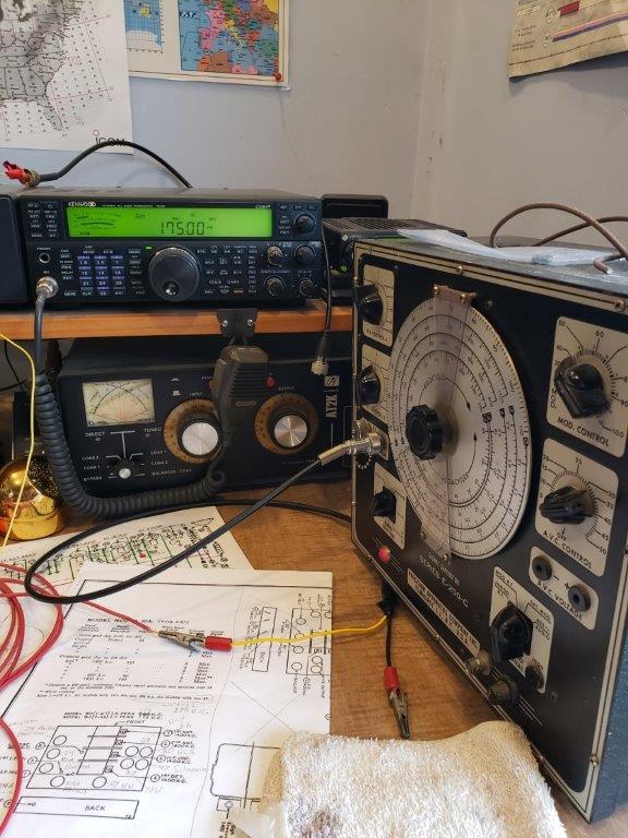
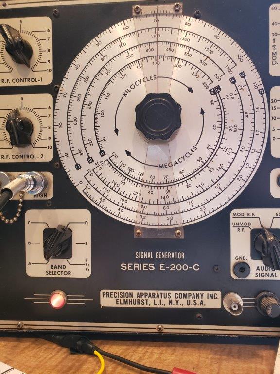
I understand that 175 is the correct IF peak for this unit (Model 90 1-47)
Now, I know I'm doing something stupid, because I'm not getting signal thru the IF; the instructions say
"Remove grid clip from 1st det." (which I did), sig generator connected to said tube grid (thru a .1 cap), ground going to chassis; I just get weird noises....I did short stator and rotor of Var. Cap. RF section and have an AC voltmeter reading output of 2nd AF.
any suggestions?
-Simon
Posts: 1,113
Threads: 14
Joined: Feb 2013
City: Irvington, NY
There a a few things to try. First connect your signal generator output to the grid cap of the 24A IF amp tube and see if you can receive the signal. This will eliminate the possibility of a problem in the first IF transformer blocking signal from the 1st detector tube.
Try tuning your signal generator above and below 175 KC while listening for output. Perhaps the IF is way out of tune which is why you are not hearing anything at 175 KC.
Removing the cap wire from the 1st detector tube and feeding signal through a 0.1 uF cap sometimes may present a problem. With no DC path to the control grid, there is no bias on the tube and it may assume any random plus or minus voltage depending on grid emission or gas content. I usually leave the cap wire on and force signal to the grid across the input tuned circuit. If the tube is operating properly, you should get IF signal through easily enough.
This is assuming that the !st detector and IF amp tubes have the proper cathode, screen grid and plate voltages applied and have been confirmed correct.
Mike, WA2YGA
Posts: 337
Threads: 13
Joined: Apr 2019
City: Greenwood
State, Province, Country: Delaware
Thanks Mike, I did as you suggest, leave the grid cap on and also tuned sig. generator up and down. I may not have went far enough the first time, because I found the signal way up at 216 ! Strong signal too, definitely not a birdie!
I thought maybe not having the 3-tube shielding might affect, so I faked it with tin foil. No difference.
Dial isn't off by much, but is off.
Perhaps I caused the IF Peak to move by removing and cleaning the Var. Cap.
I will attempt to move it back to where it belongs 175 kc.
-Simon
Posts: 1,113
Threads: 14
Joined: Feb 2013
City: Irvington, NY
Its not unusual for the IF to be off that much. Over the years, several previous owners or servicemen may have tuned the IF by ear, not using an accurate signal generator.
I have recently been working on a 1930's RME-69 receiver and could not get the crystal filter to work. Finally found the IF at 505 kc, not the correct 465. Realigning IF at 465 matched it up to the crystal freq and allowed it to work properly.
The mica compression trimmers in the IF of these radios have a lot of tuning range, so it is not difficult to align them way off freq.
The IF offset will also affect the dial calibration, so you will probably find, the dial off a similar amount. Setting to the correct IF freq should correct most if not all of any dial error.
Posts: 337
Threads: 13
Joined: Apr 2019
City: Greenwood
State, Province, Country: Delaware
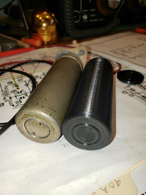
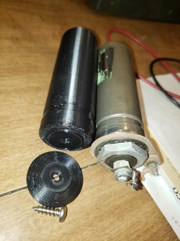
On another subject- I suspect this old (nickel?) plated electrolytic was original since it wasn't even hooked up. And, since no one here has one I printed one.
Right now, color is black, but I intend to find some paint and make it look a little bit more like the real one. Just for show, since I have the workers under the chassis.
-Simon (I'll try anything once!)
Posts: 5,011
Threads: 267
Joined: Nov 2012
City: Bandon
State, Province, Country: OR
very nice! What material did you use and what will you paint it with? Curious because I just did my first foray into 3-D printing to make a bezel.
Posts: 337
Threads: 13
Joined: Apr 2019
City: Greenwood
State, Province, Country: Delaware
Bob, it's just "PLA" plastic filament, the most common for 3D printers. We recently bought an Ender 5 Plus here at work, and I took advantage! paint- not sure what I'm gonna do there. probably pretty tough to duplicate so I might just do a gray or something....
Yes it would be cool to print bezels and knobs and stuff like that- probably never look exactly like the originals but sure enough better than nothing.
Simon
Posts: 13,776
Threads: 580
Joined: Sep 2005
City: Ferdinand
State, Province, Country: Indiana
Wow, I am impressed with the 3-D printing! 
You might consider painting it copper, like a Mershon condenser. Then print another, paint it copper also, and you'll have a matching pair. It's easier to come up with copper paint that actually looks like copper than it is to find something that looks like polished nickel.
--
Ron Ramirez
Ferdinand IN
Posts: 337
Threads: 13
Joined: Apr 2019
City: Greenwood
State, Province, Country: Delaware
That's not a bad idea Ron, I might just do that!
Simon
Posts: 337
Threads: 13
Joined: Apr 2019
City: Greenwood
State, Province, Country: Delaware
Well, Mondial Mike;
I left the clip connected to grid of the first det., and with sig gen walked the IF peak down to 175 kc. with trimmer 1,2, and 3.
Then adjusted 1400 kc per instructions, then 600 kc, then 1400 kc.
Now getting stations in narrow bandwidths on 600 and 1400, but nothing in between!
Rechecked 175 IF it's ok. Swapped 27 osc tube with 27 1st AF, no difference
I see the article "unusual No Reception problem in model 90" in the Philco Library and will check out those items listed.
Regards,
Simon
Posts: 1,113
Threads: 14
Joined: Feb 2013
City: Irvington, NY
Seems like the oscillator freq is not tracking the resonant freq of the antenna and RF coils over the full broadcast band. I wonder if someone replaced those coils with ones from a later model with 260 kc IF?
What I would try is to compare the osc freq with the dial calibration of the 90 across the broadcast band. Start at 550 on the dial and receive the osc signal on your digital comm receiver. Osc should always be 175 kc higher than dial indication. Proceed up the band and record dial and actual osc freqs every 50 kc. If the osc freq differs from dial reading by anything other than 175 kc across the band then there is a tracking problem.
Posts: 337
Threads: 13
Joined: Apr 2019
City: Greenwood
State, Province, Country: Delaware
Well your suggestion to check the osc freq tracking with the dial was a good one; I loose coupled to the osc. tube, and it went like this:
Dial Osc
600 +180
700 +189
800 +148
900 +120
1000 +95
1200 +15
1400 -74 (yes, -74)
The dial needs some set screw adjustment, but this does show the tracking is way off.
I think I shall meander the I.F. back up, and see if we can get the tracking where it should be. And, maybe reception will come back.
Thanks Mondial Mike,
Simon
Posts: 1,113
Threads: 14
Joined: Feb 2013
City: Irvington, NY
That's pretty strange. Oscillator is way off at the high end. Does the dial calibration agree with the actual reception freq?
I guess my question is if you set the dial to 1400 kc are you receiving 1400 or actually 1250? Is the oscillator trimmer on the tuning cap tightened all the way down? Seems you have much to much capacitance at the high end of the band.
So you are receiving stations at 600-800 kc but as you tune higher you lose sensitivity?
Before anything else, I would set the dial setscrew first to the correct index, as any error is multiplied at the high end of the band.
Posts: 337
Threads: 13
Joined: Apr 2019
City: Greenwood
State, Province, Country: Delaware
I did set the dial setscrew pretty close, but it needs a tad more attention.
Yes, I'm receiving stations at 550-700 approximately, then nothing till I get up to about 1200, then stations again. The dial is a little higher (or lower) than is should be, not much.
Yes, the osc. trimmer is tightend down all the way. thats the only way I could get stations at 600 and 1400. also, another trimmer is bottomed out, I forget which one.
-Simon
Users browsing this thread: 1 Guest(s)
|


