Philco 46-480 Replacing Field Coil w/ Perm Mag (I know I know)
Posts: 855
Threads: 8
Joined: Jul 2020
City: Greenlawn
State, Province, Country: NY
Hi Rev,
LOL on the perm. Your lightning rod comment reminds me of a character in the John Candy movie "The Great Outdoors" When asked how many times he was struck by lightning, the character who had a white streak in his hair replied "Sisisisisixisixisixty six times in nnininin ththththte hhhhehhead!!
Maybe that is why my hair is curlier than my 3 brothers and 2 sisters! "Old Restorer" posts the number of times that he has been electrocuted.
The fact that I made it into adulthood without being blinded, maimed or killed, other than being a little mentally ill (so my Wife tells me) is proof of a loving and benevolent God (and boy, do I owe Him!)
If i got too jargony, sorry. let me know and I can elaborate.
Do try the simple things. Wiggle the oscillator mixer tube, the 2 IF tubes and the detector tube in their sockets. If a lot of static while wiggling, clean contacts. also slowly turn the band switch to see if you get static or if the radio starts playing. Then go for the heavy stuff that I wrote about.
Good luck and keep us all posted!
"Do Justly, love Mercy and walk humbly with your God"- Micah 6:8
Best Regards,
MrFixr55
Posts: 855
Threads: 8
Joined: Jul 2020
City: Greenlawn
State, Province, Country: NY
Hi Rev,
LOL on the perm. Your lightning rod comment reminds me of a character in the John Candy movie "The Great Outdoors" When asked how many times he was struck by lightning, the character who had a white streak in his hair replied "Sisisisisixisixisixty six times in nnininin ththththte hhhhehhead!!
Maybe that is why my hair is curlier than my 3 brothers and 2 sisters! "Old Restorer" posts the number of times that he has been electrocuted.
The fact that I made it into adulthood without being blinded, maimed or killed, other than being a little mentally ill (so my Wife tells me) is proof of a loving and benevolent God (and boy, do I owe Him!)
If i got too jargony, sorry. let me know and I can elaborate, but some of my acronyms and abbreviations:
AA5- All American Five, the description for the very common 5 tube circuit consisting of a Pentagrid Mixer, IF stage, Detector and 1st Audio Tube, Audio Output (power amp) tube and Rectifier. Most folks define an AA5 as an AC-DC set as opposed to one with a power transformer.
Xformer = Transformer (X = trans)
OPT = Output Transformer
Cap= Capacitor (condenser)
OSC= Oscillator (your radio has a separate Oscillator and Mixer as opposed to the "Pentagrid" mixer common in "AA5" radios
IF = Intermediate Frequency
SMD= Silver Mica Disease Many IF transformer assemblies from newer (about 1948 or later) radios had built in capacitors of about 100pF (picoFarad). Apparently, the mica would crack, the silver would corrode and the cap would short. This also happens to mica caps with molded plastic cases.
Do try the simple things. Wiggle the oscillator mixer tube, the 2 IF tubes and the detector tube in their sockets. If a lot of static while wiggling, clean contacts. also slowly turn the band switch to see if you get static or if the radio starts playing. Then go for the heavy stuff that I wrote about.
Good luck and keep us all posted!
"Do Justly, love Mercy and walk humbly with your God"- Micah 6:8
Best Regards,
MrFixr55
Posts: 33
Threads: 2
Joined: Sep 2022
City: Ventura
State, Province, Country: CA
Haha! Yeah I know the character! Pretty much!
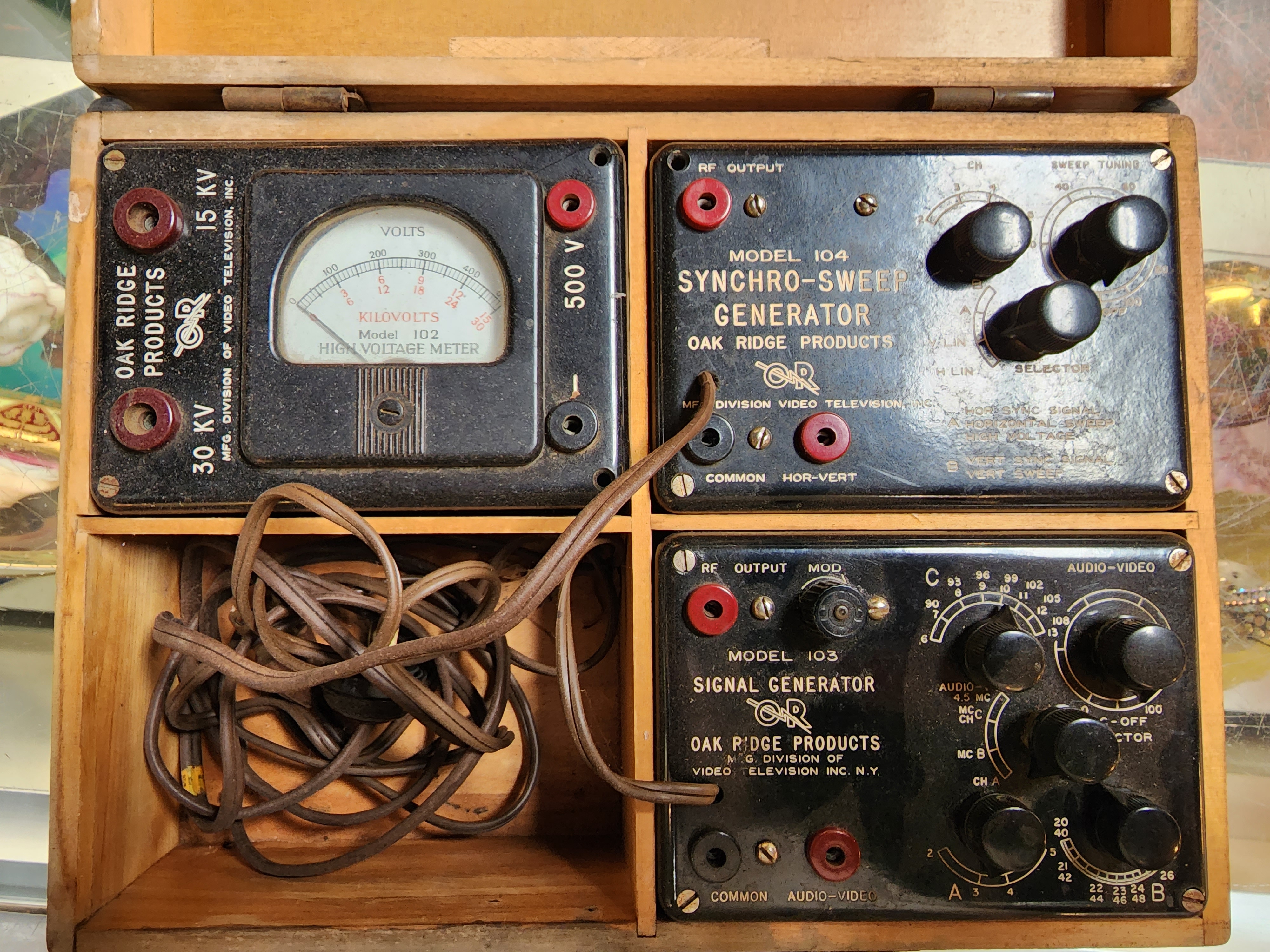
Alright, good news, bad news situation. Bad news is the fancy signal generator I was thinking of is a doorstop. Good news is, I found this set rattling around in the shed.

Hasn't been used in umpteen years, but should do the truck, right?
Posts: 13,776
Threads: 580
Joined: Sep 2005
City: Ferdinand
State, Province, Country: Indiana
Wrong. That looks more suited for TV and (possibly) FM work.
If a signal generator for vintage radios is what you are looking for, then what you need is something that will output amplitude modulated (AM) signals from the IF range of your radio (around 450-455 kHz) up to around 30 MHz.
--
Ron Ramirez
Ferdinand IN
Posts: 33
Threads: 2
Joined: Sep 2022
City: Ventura
State, Province, Country: CA
Ron-
Wellp glad I asked first haha! Back to the drawing board.
-Rev
Posts: 33
Threads: 2
Joined: Sep 2022
City: Ventura
State, Province, Country: CA
Alright, well I've cleaned the ever lovin buhjeesus outta this thing, (carefully tho) and still I'm getting nothing from it on any band. I even hooked up one of those Bluetooth devices that broadcast FM to your car radio and set it right next to it, thinking maybe I just wasn't getting reception at all. Alas, nothing. Still trying to source a signal generator.
Do I remember someone saying they knew how to Jerry rig one?
Posts: 855
Threads: 8
Joined: Jul 2020
City: Greenlawn
State, Province, Country: NY
Hi RetroRev,
That wood case signal generator looks like it can generate FM signals, but the IF Output of it is likely 4.5MHz and the FM IF on your set is 9.1MHz (?). Most FM Sets are 10 MHz IF
I have not actually done it, but if you have another working radio, you can "tap" off signals from it to the radio under test. It is important that both radios have the same or very close IF frequencies. Most, but not all AM sets of the period have IF sections tuned to 455KHz. Per the N/A schematic, your set has a 460 KHz IF. However, the alignment instructions in the schematic state to set the signal generator to 455KHz. To be safe, both radios should be "transformer powered. If the "Tester Set" (The one being used as the "signal generator") is an AC-DC Set, use an isolation transformer or ensure that the chassis is at ground potential and not hot. Verify that the set under test does not have any leaky caps between the AC Line and chassis. In either case, ensure that that chassis is close to ground potential and connect the 2 chassis together. Connect a 100 pF capacitor to the plate of the IF Amp Tube of the "Tester Set". Connect the other end of that "cap" to a meter test lead (Shielding? Shielding? We don't need no stinking shielding!").
Prior to testing, verify that the Audio section of the set under test is still working, then get the stray cats out. In addition, test or replace the 6H6 Detector tube. This tube serves as both AM detector and FM Discriminator. In addition, "Ohm out" the IF and oscillator transformers and verify B+ at the plates of the IF, Mixer and Oscillator tubes.
Another test to perform is to tune the Tester set to a station in the middle of the broadcast band, use a wire wound around the oscillator tube of the set under test and loosely coupled to the antenna of the Tester Set, then tune the set under test across the AM Band. If while "sweeping" the dial of the set under test, howling or loss of signal occurs in the tester set, the local oscillator of the set under test is working. If not, the Oscillator is dead, and the cause of your issue.
Tune the Tester set to a station. Fully mesh the tuning cap of the set under test.
Now, with the chassis of the 2 radios connected and both radios powered up, attempt to inject the signal into the grid of the 2nd IF tube of the set under test. If signal, howling, etc. is heard, the 2nd IF stage is either good or partially good. If no joy, further troubleshoot that stage. Look for shorted caps (capacitors), especially any old paper caps or mica caps that you did not change. (Most folks don't change the mica caps, but they do go bad.). If a signal is heard, then work your way backward through the 1st IF and Mixer stages. In addition, follow the alignment steps in the schematic.
Hope this helps. Good luck!
"Do Justly, love Mercy and walk humbly with your God"- Micah 6:8
Best Regards,
MrFixr55
Posts: 33
Threads: 2
Joined: Sep 2022
City: Ventura
State, Province, Country: CA
Whelp still looking for a proper signal generator locally, but after doing all the tests I can without one, I've still got nada from the radio. Not even static while tuning or anything short of a small pop when switching bands, so I'm leaning towards this thing either being dead, or improperly wired somewhere that I'm just not seeing..
Posts: 100
Threads: 13
Joined: May 2020
City: Clemmons
State, Province, Country: NC
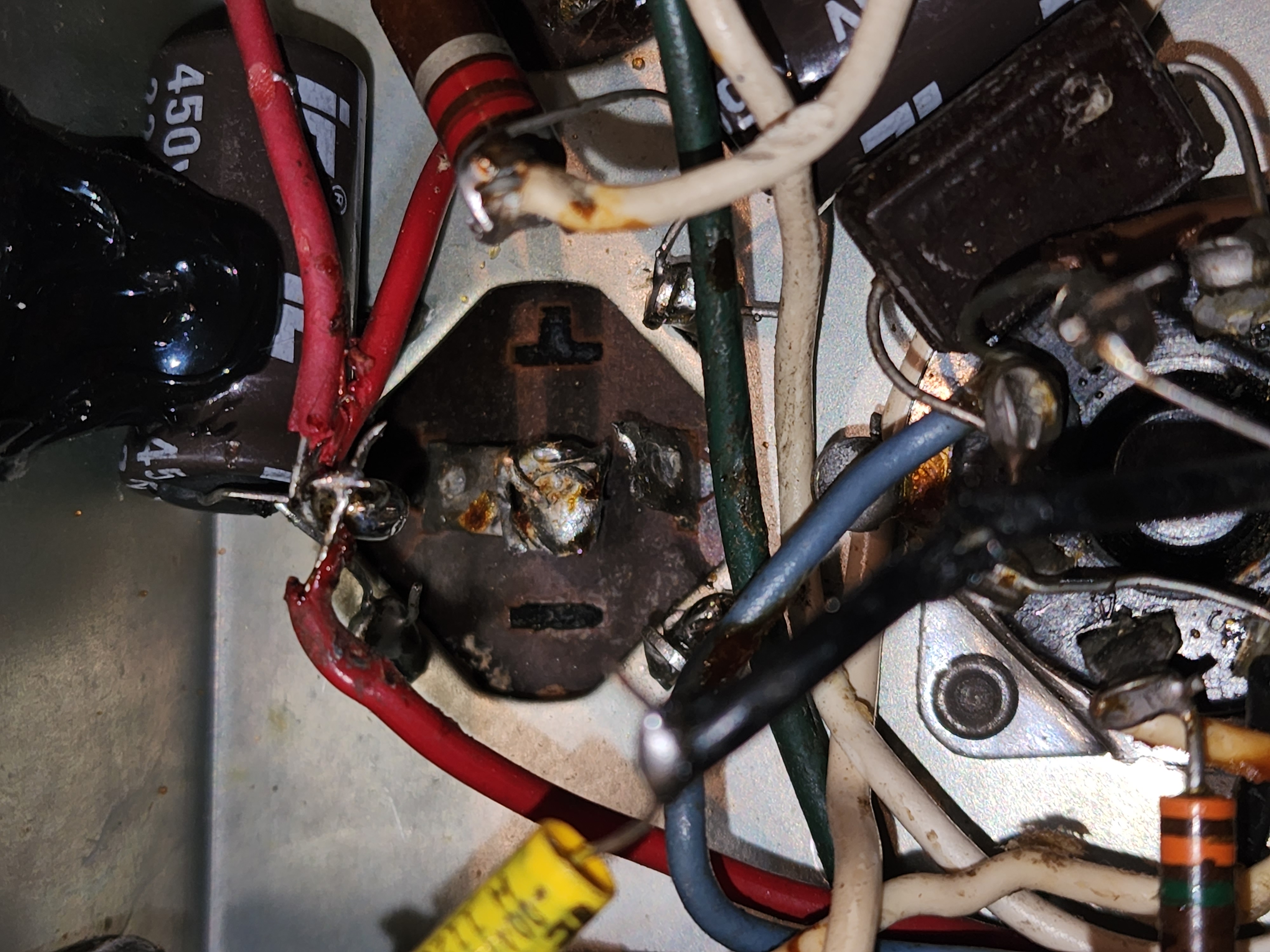
Check c60/c61 lytics, one might be installed backwards, maybe both looking at your pic, negative should be to ground if that is what I see, not familiar with this radio, but check it. Both should be negative to ground.
Posts: 33
Threads: 2
Joined: Sep 2022
City: Ventura
State, Province, Country: CA
It looks like they are both neg to ground, but I did just notice, there's nothing connected to this condenser (philco part number 30-2555)

Posts: 100
Threads: 13
Joined: May 2020
City: Clemmons
State, Province, Country: NC
The two side by side connected to the resistor, one is not negative to ground, and the resistor is not the correct valuei if I am reading the schema correctly. All three negative go to ground, one at least is not.
(This post was last modified: 10-02-2022, 07:00 PM by radio1.)
Posts: 33
Threads: 2
Joined: Sep 2022
City: Ventura
State, Province, Country: CA
Oh I see what you're saying now. I was looking in the way wrong area.
My schematic is rather hard to read, even blown up.
On R33, is that 6200?
Posts: 100
Threads: 13
Joined: May 2020
City: Clemmons
State, Province, Country: NC
Looks like 8200 so maybe correct, go over it carefully, trace every point, + and -.
Posts: 33
Threads: 2
Joined: Sep 2022
City: Ventura
State, Province, Country: CA
Ok so c60/c61 are neg to ground, the one that's got the white and green to it is c59. Looks like last guy just put the resistor between the wrong caps.. maybe..
Posts: 100
Threads: 13
Joined: May 2020
City: Clemmons
State, Province, Country: NC
If the one with white/green has the positive attached to ground, it's mucked up, something is wrong.
Users browsing this thread: 1 Guest(s)
|


