New Project: 1934 Colonial 662 (corrected model)
Posts: 1,275
Threads: 44
Joined: Nov 2017
City: Menlo Park
State, Province, Country: CA
Hi Folks,
It's been a little while, but a new radio landed at my doorstep: a slightly scuffed Colonial 651, which the internet tells me hails from 1934. Aside from extracting a mouse nest, the set was in good condition. It's generally unmolested as far as I can make out from an initial assessment. It's a 5 tube ac set, 6A7, 78, 75, 41 output tube and 84 rectifier. The latter bears a dealer test sticker dated 1942, from a dealer in Oakland, CA.
Pictures to follow, once I've resized them.
Ed
I don't hold with furniture that talks.
(This post was last modified: 07-31-2023, 02:39 PM by EdHolland.)
Posts: 1,275
Threads: 44
Joined: Nov 2017
City: Menlo Park
State, Province, Country: CA
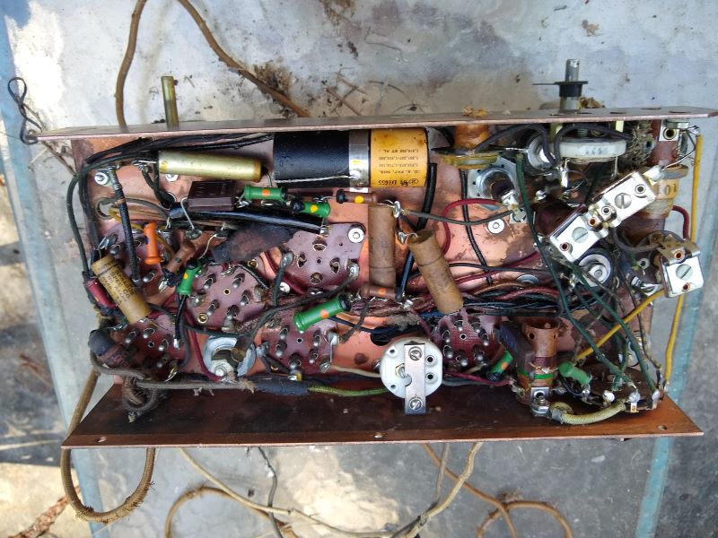
A few pictures:
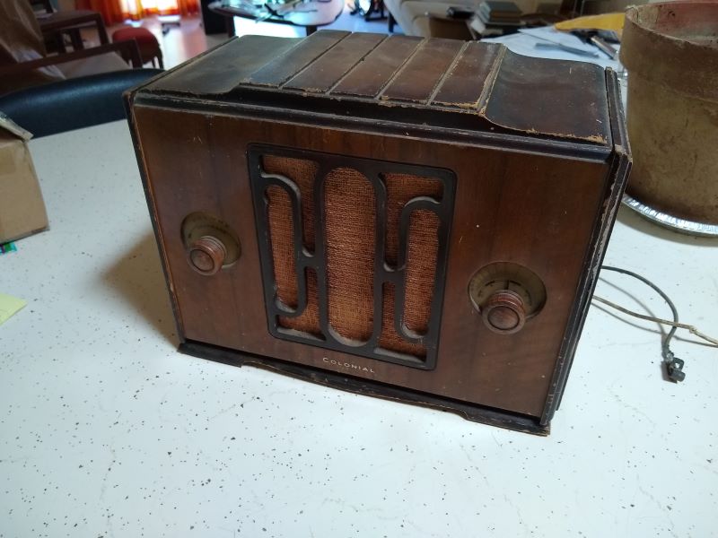
Signs of previous inhabitants...
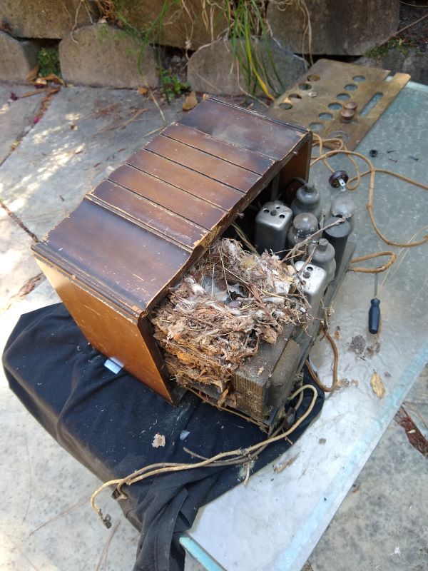
Not too bad underneath all that!
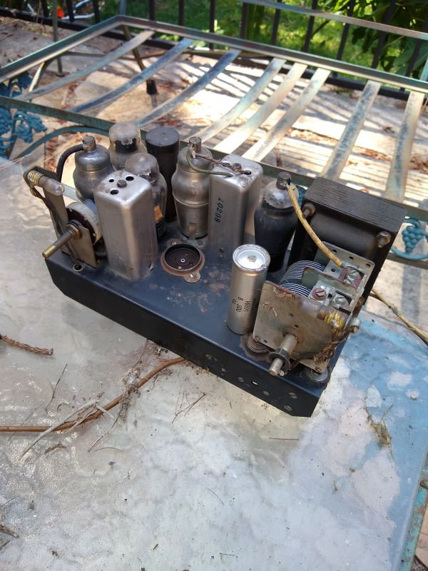
Below decks:
I don't hold with furniture that talks.
Posts: 2,005
Threads: 361
Joined: Jun 2010
City: Dover, OH
I think my buddy has one of those Colonials sitting on a shelf.
No matter where you go, there you are.
Posts: 1,426
Threads: 88
Joined: May 2008
City: Omak
State, Province, Country: WA
Hello Ed,
Nice little set it reminds me of my little Philco !
Sincerely Richard
Posts: 855
Threads: 8
Joined: Jul 2020
City: Greenlawn
State, Province, Country: NY
Nice set Ed! Hose it off and disinfect really well. Chassis finish looks really good! Reminds me of my Crosley 5C2 but yours is much better built, especially having a transformer. I wonder why the 84 was not more popular with small radios. It would give sufficient power and save a filament winding. Interesting enough, I just looked at the schematic and they do, in fact, have a separate filament winding for the 84. Any of the Philco schematics using the 84 that I have looked at, including my 41-250, use the same winding for the 84 filament as the do for the other tubes. They can do so as the 84 cathode is insulated from the filaments. Per the RCA Receiving Tube Manual (RC12), the maximum potential difference between heater and cathode is 500V. The main issue in using an 84 is that the tube delivers a maximum of 50mA vs the 125mA of an 80, but for a set with a single output tube, it should be sufficient. (Heck, the 41-250 has P-P 41s, but at 180V, I am sure that the output is much lower than if driven by 250V.
"Do Justly, love Mercy and walk humbly with your God"- Micah 6:8
Best Regards,
MrFixr55
(This post was last modified: 07-26-2023, 09:55 AM by MrFixr55.)
Posts: 1,275
Threads: 44
Joined: Nov 2017
City: Menlo Park
State, Province, Country: CA
Thanks folks.
I'll be careful with clean up. It seems the Wireless mouse existed long before computers...
For a small set, I'm impressed with the build quality. Even the underside of the cabinet is sculpted with a curved profile, the chassis is copper plated on the underside, and painted on the top. Tuning has a reduction drive.
Ed
I don't hold with furniture that talks.
Posts: 4,611
Threads: 51
Joined: Sep 2008
City: Sandwick, BC, CA
The current rating is really dependent on whatever the B+ voltage is, think of the #84 as a six pin 6X5G, basically useful for radios of a lower tube count, or car radios. Interesting that Colonial used a power transformer with a separate rectifier tube winding, does it put out 6.3 volts or 5 volts? Colonial used to manufacture radios for Sears, in fact I think they were either wholly, or majority owned by Sears.
Regards
Arran
Posts: 855
Threads: 8
Joined: Jul 2020
City: Greenlawn
State, Province, Country: NY
Hi Aran,
Yes, the 84 / 6Z4 is a 5 pin (UY Base). It is used in quite a few Philco table radios (41-255, etc), as Philco used them in car radios. I think that Philco was an early convert to 6Volt tubes because of their car radio business. This tube was eventually replaced by the octal 6X5 or the 7 pin miniature 6X4. These all have a max DC current between 40 and 50 mA.
I think that there were several companies that built for Silvertone, including Arvin, Colonial, Detrola, Emerson, Howard and supposedly Zenith.
"Do Justly, love Mercy and walk humbly with your God"- Micah 6:8
Best Regards,
MrFixr55
Posts: 1,275
Threads: 44
Joined: Nov 2017
City: Menlo Park
State, Province, Country: CA
I'll follow up with more information about the rectifier wiring and transformer voltages this weekend. Hopefully there will be time for a transformer test. Anything further will require attention to the caps.
Choices are difficult - I'm also working on another acquisition, in the form of a nice Raleigh bicycle picked up locally for a good price.
I don't hold with furniture that talks.
Posts: 1,275
Threads: 44
Joined: Nov 2017
City: Menlo Park
State, Province, Country: CA
Quick update, including a correction first. The radio had a sticker on the inside of the top, declaring the model as 662 (Not 651 as stated. From what I can find, there is very little difference, Tube lineup, chassis layout and band coverage is very similar. It may be a year older than the 1934 mentioned in my first post.
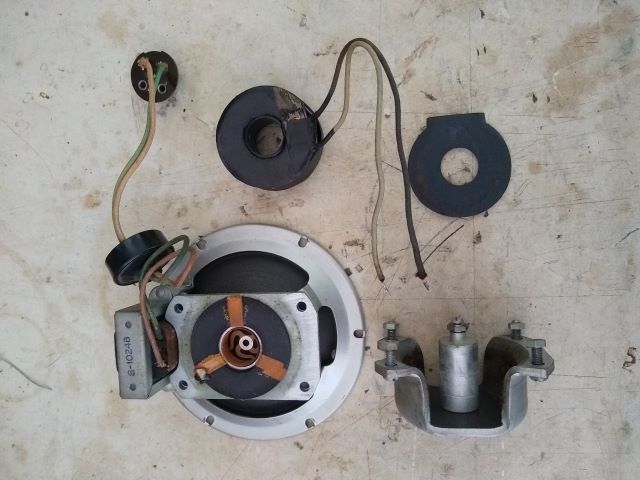
On to technical matters. I tested the speaker - output transformer and voice coil are good, but the field coil is open. Fortunately, the speaker is held together with nuts and bolts, so I have been able to dismantle and free up the coil, but stopped there for now. Next thing is to see if I have the required wire, and set about the rewind.
Ed
I don't hold with furniture that talks.
Posts: 1,275
Threads: 44
Joined: Nov 2017
City: Menlo Park
State, Province, Country: CA
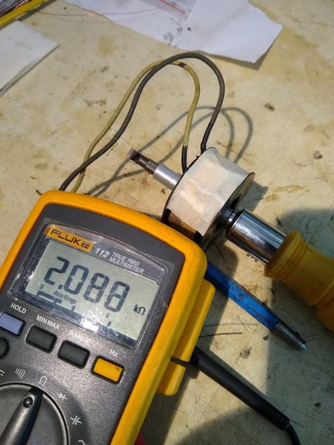
The Gods have been kind. I peeled the paper covering and very gently teased open to the solder joints between the leadout wires and the coil winding. the break was right there, and enough wire remained to allow the connection to be repaired. Field coil now measures spot on the 2100 ohms on the rather fuzzy schematic. 
Edit - the difference between mode l651 abd 662 has been revealed. 651has shortwave coverage from 5500 to 18 MHz, whereas 662 covers 1600 to ~5200 kHz. Otherwise, they are the same.
I don't hold with furniture that talks.
(This post was last modified: 07-30-2023, 10:55 PM by EdHolland.)
Posts: 1,275
Threads: 44
Joined: Nov 2017
City: Menlo Park
State, Province, Country: CA
A few pictures:
Checking the repair before adding the cloth tape and original card protection
All the bits ready for reassembly:
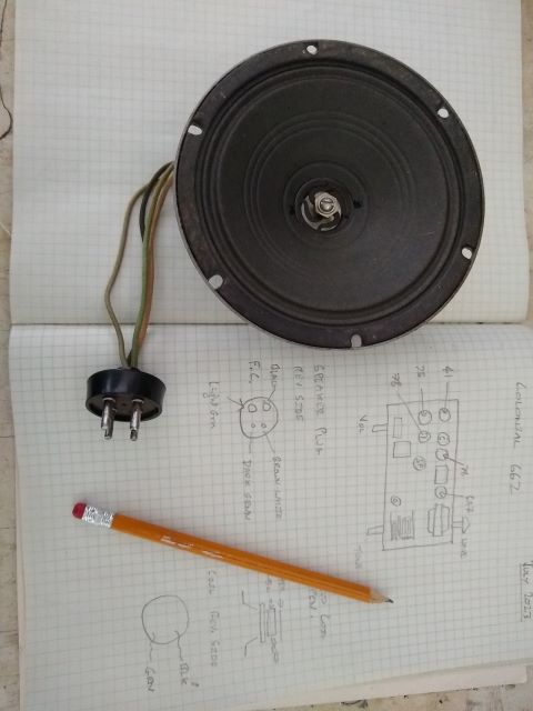
All complete. Quite a bit of care was required to realign the parts to ensure the voice coil was clear of the polepieces.
I don't hold with furniture that talks.
Posts: 1,842
Threads: 140
Joined: Jan 2013
City: Westland, MI
Nice work, Ed! Take care and BE HEALTHY! Gary
"Don't pity the dead, pity the living, above all, those living without love."
Professor Albus Dumbledore
Gary - Westland Michigan
Posts: 312
Threads: 30
Joined: Jul 2017
City: Hay Lakes, Alberta,Canada
Nice work Ed!
I have taken a shine to the compact depression sets as of late, buying several Northern Electric, DeForest Crosley and Electrohome's during the last three years. Early in my collecting life, I overlooked them, preferring the large, impressive (and space consuming) consoles.
Posts: 1,275
Threads: 44
Joined: Nov 2017
City: Menlo Park
State, Province, Country: CA
Progress 
I made continuity checks on the power transformer, and checked the power switch in the volume control. These always seem to need a clean, such was the case here. With these basics done, I pulled the valves and powered up through the dim bulb tester. No problems indicated, and all voltages from the transformer looked appropriate. Keen to test, I substituted the electrolytics with temporary "tack in" caps, disconnecting the originals. With just the rectifier, B+ came up nicely, no issues on the dim-bulb whatsoever. I replaced all the valves and commenced a careful power-up. Slight hiss and crackle from the speaker, but no stations. Lots of crackling from the wave change switch - a cleanup improved this, but still no stations. As with my previous 6A7 /6A8 set, I suspect the oscillator isn't working thanks to drifted/leaky components. I did inject 480 kHz through the IF, and this, and the audio stage are operating.
Paper cap replacement/restuff and resistor checks next, but this is encouraging stuff.
Ed
I don't hold with furniture that talks.
Users browsing this thread: 1 Guest(s)
|


