Zenith Model 7 -S-204 "Waltons"
Posts: 79
Threads: 24
Joined: Jan 2018
City: Kaiapoi New Zealand
Hi everyone,
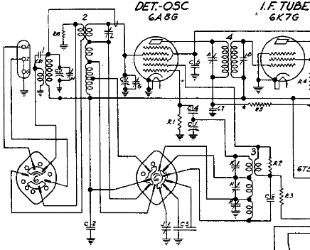
I'm working on this model of Zenith (Riders 1938 WXYZ page 105 ).I have got an i.f. signal through to the speaker with the sig gen connected to the grid of the 6A8 which suggests that all is as it should be in the following sections of the set.
But the "pre 6A8 " tuned sections are proving a problem.I have identified the connections to the first aerial coil located, unshielded, across the bottom of the chassis and from there to the "gimmick " coiled round the grid lead to the 6A8.
The connections to the next coil ,shielded in a can , next to the oscillator coil similarly shielded in a can which is closest to the dial are a mystery to me.Looking into the chassis with the dial away from me there are seven tags on this coil which I have numbered 1 - 7 starting at 11 o'clock for 1 progressing clockwise through to seven. Seven has a red fabric covered wire to it from the wavechange switch. Tag 1 has a green fabric covered wire and the heavy bare wire to the middle gang of the tuning condenser connected to it.
I'm hoping that someone may have worked on this set and kept notes perhaps on which tag connects to where on this coil .
Also on my set the wave change switch moves "too smoothly" from Police to Broadcast.There is no feeling of detent between sections leading me to wonder if this is a switch fault .Is there an owner of one of theses sets who can tell me if there should be a definite "click" between sections as the switch rotates? The "shutter " in the dial works correctly but the lack of "clunk clunk clunk " on rotation I feel is suspicious.
All contributions welcome and thanks to all. Cheers.
Posts: 597
Threads: 8
Joined: Apr 2018
City: S. Dartmouth
State, Province, Country: MA

The schematic shows the secondary of the tuning coil #2 to be progressively wound and tapped for the bands. As the bands increase in frequency there is fewer windings less resistance. Therefore using a ohmmeter can detect what wires go where. The same is relatively true for the two other coils the antenna input and the oscillator coil.
If there is no "feeling" of a detent the likely the detent ball is missing or a friction blade has broken, repair as needed or go to Classifieds and post a WTB for a band switch for this model.
Any of the coils could have poor connections or open windings, so if reading the full length of the coil is open locate the open coil and either rewind or request in the classified for a Wanted to Buy.
Though this chassis is used in other models because it is a "Waltons" chassis expect a premium for the part(s).
GL
Chas
Pliny the younger
“nihil novum nihil varium nihil quod non semel spectasse sufficiat”
Posts: 79
Threads: 24
Joined: Jan 2018
City: Kaiapoi New Zealand
Hi Chas ,
Thank you for your helpful reply . I am much closer now to figuring out which coil tags are connected to what. And , yes, the ohmmeter readings do provide clues.
I presume that ,when on broadcast , all the windings on the secondary of coil #2 are in circuit seeing as broadcast is the lowest frequency band the radio tunes to. Thanks for the pointers there.
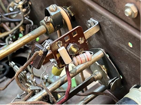
Another mystery has revealed itself in the meantime. One of the leads to Cap 21 which links the tops of the primary and secondary windings of coil#1 and which sits in the top of coil#1, has corroded away so that part of the circuit was open circuit.
Looking to replace this cap I found when I checked the schematic (a slightly blurry Radiomuseum one ) I found it listed ( in a separate box on the schematic above the R16 listing) as 10 mfd ceramic. Certainly it is ceramic but the capacity at 10 mfd seems very high, especially for such a physically small capacitor. Could the 10mfd be a misprint? If 10mfd is correct why is it ceramic? What should I replace it with? Thanks for your help with this set. And thanks to the Phorum for facilitating this kind of assistance. I'd be lost without it.
Posts: 597
Threads: 8
Joined: Apr 2018
City: S. Dartmouth
State, Province, Country: MA
"10 mfd ceramic", 10 mmfd or more commonly 10pf. This should be a cylindrical cap that looks more like a resistor. If the lead is corroded off it will have to be replaced. A silver mica will work too or a disc ceramic.
If the cap is holding up progress, a temporary solution is the twist two lengths of #22 solid plastic hook wire together about 1-1/4 inches should be enough for 10pf. Obviously a bit inductive too, but it work until the correct component arrives...
Pliny the younger
“nihil novum nihil varium nihil quod non semel spectasse sufficiat”
(This post was last modified: 09-02-2023, 12:18 AM by Chas.)
Posts: 79
Threads: 24
Joined: Jan 2018
City: Kaiapoi New Zealand
Hi Chas,
Thanks for your very prompt reply.Yes, I thought that 10 mfd was a bit odd. 10pf sounds much more realistic. The ceramic cap, hanging on by one lead did indeed look like a resistor. I have made progress with the set after cleaning the switch contacts and am now getting a m.w.signal from aerial to speaker. Someone has replaced the output transformer but the output was very muted even though the 6F6 had the right bias on both cathode and grid and was drawing about the right current.The secondary of this obviously very new xformer had three leads,presumably to match speakers of different impedance. Anyway I swapped two leads over - instant lift in volume! So thanks again for your help with this set . I'll be checking voltages and valves (oops! ...) tubes as the process of tweaking continues. (Just in passing - any thoughts on why a ceramic capacitor was specified there? ) Cheers.
Posts: 3,102
Threads: 54
Joined: Apr 2011
City: Lexington, KY
There is a very common RF coil failure in the front end of these chassis. Fortunately there are a couple of common inductors you can order to replace it. When I get home Sunday or Monday and have access to my computer and schematics I'll post the problem coil and fix.
John KK4ZLF
Lexington, KY
"illegitimis non carborundum"
Posts: 833
Threads: 36
Joined: Feb 2015
City: Roseville, MN
Hi Antipodal,
Thought I would chip in my opinion on why the ceramic. When I consider something like this I think "follow the money". Back in those days mica caps of that value were probably difficult to find and difficult to manufacture, pay big bucks to obtain. Another solution was to use the twisted pair wire but the drawback is not accurate enough. Ceramic was, and probably still is, the right solution, although temperature stability is an issue. But that can be accounted for. There's my theory. GL with the restoration.
Posts: 3,102
Threads: 54
Joined: Apr 2011
City: Lexington, KY
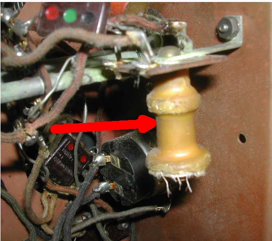
I'm sorry, the RF Choke I was thinking of is only used on the 7-J, 9-S, 12-S, and 15-S 1938 models. Those are the only chassis with an RF stage, the 7-S eliminated the RF stage for an eye tube. Anyway, for those interested and ever working on a 1938 Zenith chassis the following RF Choke is common mouse food:

Fortunately you can use a couple of inductors from Mouser to replace this:
2500uH for the large portion:
https://www.mouser.com/ProductDetail/434-XHBCC-252J-02
and 500uH for the small portion
https://www.mouser.com/ProductDetail/807-2500R-14J

John KK4ZLF
Lexington, KY
"illegitimis non carborundum"
Posts: 79
Threads: 24
Joined: Jan 2018
City: Kaiapoi New Zealand
Hi everyone,
Thanks for your help given with this set so far. I am still trying to unravel the mysteries of what should be the simplest and most straightforward part of this set i.e. the pre 6A8 tuning section.
Someone has done some repairs on the #1coil ( and indeed on a lot of the rest of the set including fitting a new power transformer ) and left me in doubt about which is the primary and which the secondary.The repairs were brought about , i think, because the fine wires running down the inside of the coil had broken , perhaps because of greenspot or maybe lightning static build up. Either way plastic coated hookup wire was used to re-link coils to tags and lots of sticky insulating tape were wound round the coil.Taking off the insulating tape I may have inadvertently broken the fine coil wire attached to the black hookup wire - or it may have been open circuit anyway.
But now I am ready to resolder and put it all back together.
However one point of doubt has arisen.One coil, which I thought to be the primary has an ohmmeter reading of 26 ohms. The other has a reading of 2 ohms.Can phorum members clear this up for me ? Which would you say was the primary and which the secondary? Also, is 26 ohms on the high side for a coil in this position or does it seem about right?
I hope I have made this clear. Thanks everyone for your assistance and cheers.
Posts: 79
Threads: 24
Joined: Jan 2018
City: Kaiapoi New Zealand
Hi everyone,
I am still wrestling with the front end of this set. On the schematic (which Chas helpfully put up )the aerial connector has three terminals. One is labelled "A" , presumably for antenna . One is labelled "E" for earth. The one in the middle is labelled "Z".Can anyone tell me what "Z" stands for?
Also, on the printed paper schematic there is a dotted line shown between "Z" and earth terminals. This dotting is not clear on the schematic Chas has uploaded but it ( the dotted line between "Z" and earth on the paper schematic)has me confused. Can anyone throw light on this dotting?Does it mean that a busbar should /could be put between "Z" and earth and if so under what conditions?
Thanks everyone and cheers.
Posts: 833
Threads: 36
Joined: Feb 2015
City: Roseville, MN
The dashed line indicates an optional connection since the radio is subject to many environments and has multiple bands with various lengths of antennae. The connection usually has a direct effect on the noise interference recieved.
On the schematic above it looks to me like the terminals are labeled A, Z and G. Maybe somewhere else in the schematic there is a clue to what Z stands for. It's up to the schematic editors as to what to use. Often they are not associated with the manufacturer.
The antenna coils are generally step-up transformers. Considering this, a noise interference signal would also get stepped up. It's a delicate balance.
(This post was last modified: 09-17-2023, 08:58 AM by RodB.)
Posts: 597
Threads: 8
Joined: Apr 2018
City: S. Dartmouth
State, Province, Country: MA
The A-Z-G terminals are used this way with a single wire antenna:
Connect A to the single wire antenna, connect Z to G and connect G to ground (Earth).
With a doublet antenna transmission line using two twisted wires, connect one wire to A and the other wire to Z, do not connect Z to G. Keep the G connected to earth ground.
The doublet antenna commonly uses a twisted pair of wires and is used as a transmission line to the antenna. The type of connection at the antenna will vary as the transmission line has a characteristic impedance, the antenna connection must match that, yet be broadband for all the shortwave frequencies. The twisted pair transmission line cancels out most noises from inside the home, a good choice if the radio is located well inside the home.
Pliny the younger
“nihil novum nihil varium nihil quod non semel spectasse sufficiat”
(This post was last modified: 09-18-2023, 09:30 AM by Chas.)
Posts: 79
Threads: 24
Joined: Jan 2018
City: Kaiapoi New Zealand
Thank you fellows, That all makes sense.Back to the shed with its single wire antenna!
Posts: 79
Threads: 24
Joined: Jan 2018
City: Kaiapoi New Zealand
Back from the shed!
Just a thought -can we assume that the wave change switch as shown in the schematic is in the "broadcast " position ? If this is so with a single wire antenna on "A" and "Z" grounded to "G" the signal will go through the primary of coil#1 and thence to earth.
If my reading of the switch wafers and positions is correct, with the switch in the "broadcast" position the primary of coil#2 is floating ,earthed through R16 (1k ohms )but not connected in any other way to any other part of the circuit.
So "broadcast " signals only reach the grid of the 6A8 through the gimmick ,the primary of coil 2 being not connected to any signal path.
Have I read this correctly?
The reason I ask is because I have concluded that the wave change switch is damaged, as mentioned in a previous post, and that is not making sorting this front end any easier.Thanks everyone.
Users browsing this thread: 1 Guest(s)
|


