Need a decent schematic Scott Laureate
Posts: 1,106
Threads: 88
Joined: Jun 2011
City: Tacoma
State, Province, Country: Washington
and a good pic of the underside of the power supply chassis, concentrating on the area of the filter bank.
I just got in the power supply for a Laureate I bought a while back, and the PS has been modified (according to the schematic I have, things have been ADDED?? There appears to be an extra choke, an extra high power resistor and an extra wire coming from the cathodes of the 5U4's. I would like to put this thing back to stock if I can. I'm presuming that all this stuff was added to replace the speaker field coil??
Posts: 661
Threads: 141
Joined: Jun 2011
City: Elko,MN.
I feel your pain,
I have had some real basket cases on my bench that were modified heavily.
WHat a nightmare to work on.
You helped me out with that philco a couple weeks ago.
Wish I could help you out Brenda.
Good luck with that one.
I am working on a battery set now, and they are definately not what I am used to.
Has a vibrator that buzzes. Is it supposed to do that, I don't know.
Anyway, good luck on your search.
murf
Posts: 453
Threads: 29
Joined: Sep 2009
City: Lapeer
State, Province, Country: MI
Hi BrendaAnn, You may have already seen this link http://oldradiocrazy.com/?p=4582
There is a pic of the underside which you may be able to zoom in and have a look-see. Joe
Joe
Matthew 16:26 "For what does it profit a man if he gain the whole world, yet lose his own soul?"
Posts: 453
Threads: 29
Joined: Sep 2009
City: Lapeer
State, Province, Country: MI
Riders does have the schematic in volume 14 but the electronic index mislabels it as HiFi A-W. It begins at the E. H. Scott page 14-28, Where it is identified as "Laureate". The schematic looks pretty good. Joe
Joe
Matthew 16:26 "For what does it profit a man if he gain the whole world, yet lose his own soul?"
(This post was last modified: 01-25-2014, 04:25 PM by Joe Rossi.)
Posts: 13,776
Threads: 580
Joined: Sep 2005
City: Ferdinand
State, Province, Country: Indiana
Brenda
Are you aware of this site?
http://ehscott.ning.com/
They not only have their own forum and photo gallery, but also schematics/service info.
--
Ron Ramirez
Ferdinand IN
Posts: 599
Threads: 24
Joined: Jan 2014
City: Edmonton AB CA
Brenda:
The EH Scott site that Ron mentions has a great bunch of guys that would be happy to help you out. I am a member though haven't been active for sometime. I may have a schematic but will have to try to find it. We moved a while back and I am still rediscovering lost treasures.
Gregb
Posts: 1,106
Threads: 88
Joined: Jun 2011
City: Tacoma
State, Province, Country: Washington
Thanks. I did find that site this morning. I see Norm Braithwaite is a member over there. He's a great source, and I had almost forgotten that he had helped me out before. I've applied for membership on that forum, and also dropped Norm a line about pics.
Posts: 1,106
Threads: 88
Joined: Jun 2011
City: Tacoma
State, Province, Country: Washington
Eeeeeeeekkkk!
Well, I replaced the 'lytics in this beastie, at least the ones in the PS unit. I connected things back up the way the last 'tech' had them, just to see if anything would work.
I got good B+ to everything, but connecting an output transformer to the proper connections gave no love. So, I had to open up the tuner chassis to see what was up with the output section. When I did, I got a big surprise... the ugliest kludge of power resistors and lytics I've ever seen... all just hanging there in midair. :/ I have no idea what all that carp is, I'll have to try to figure it out. I couldn't find my shop camera tonight, so I'll have to post some pics of the mess tomorrow.
I did find the reason there was no audio out of the transformer: This tuner has a huge transformer mounted on the back of it. I had no idea what it was for till I opened the bottom, but once I had done that, I saw that it was a high fidelity audio output transformer. I had thought it to possibly have something to do with the phono input, but nope. It's connected to the 6L6's. Connecting a speaker to it gave me sound, but very distorted sound. Replacing the coupling caps to the driver stage cleaned it up, and it sounds great. I still want to try to put it all back to stock if I can, but at least I know it does make radio noises.
Work to do.. total recap.
Additional work to do: SW is virtually deaf, likely in need of a front end alignment, though everything seems to come in on the proper frequencies.
FM isn't deaf, but neither does it track properly. It tracks high on the low end, and low on the high end, and that with the LO trimmer set to minimum capacitance. So, gotta figure that out, too. Also, though it's not deaf, the RF amp section does zilch. This could be a dead tube, since it seems to be an odd tube, and isn't used in any other bands.
AM... that's fantastic. I hear stations I've never heard before on there, and the fidelity/bandwidth switch is great. Gonna love it when I get this thing all up and running. Once I do, I'll have to get to work on that 45MHz FM transmitter I promised Ron I'd design, so I have something to listen to on the FM. 
Posts: 2,569
Threads: 336
Joined: Jun 2013
City: lawrenceville nj
good job Brenda   
with or with out schematics you push your talents to the extreme
well done  
sam
Posts: 661
Threads: 141
Joined: Jun 2011
City: Elko,MN.
You are a brave soul Brenda.
I know if anyone can do it, you can.
Everything else will seem easy after completing this monster.
murf
Posts: 1,106
Threads: 88
Joined: Jun 2011
City: Tacoma
State, Province, Country: Washington
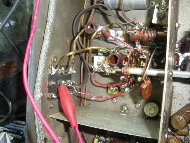
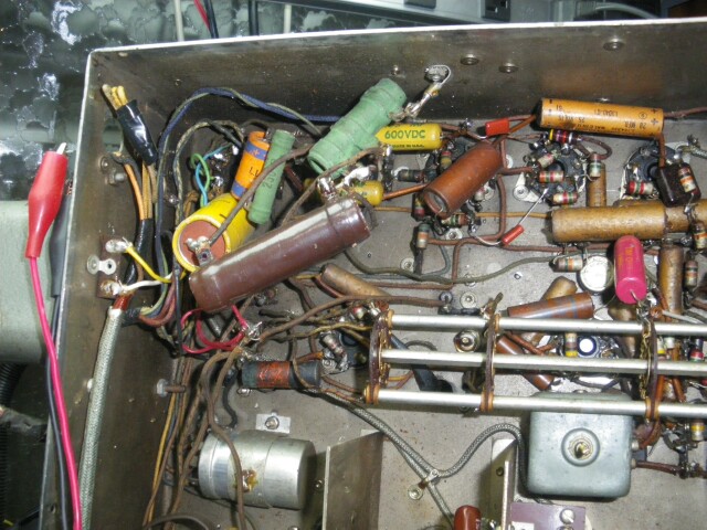
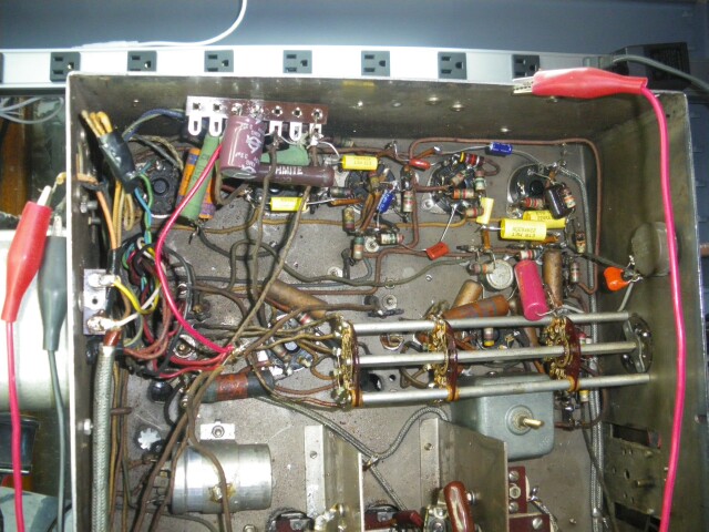
Here are the pics I said I'd post. You can see a portion of the mess under the tuner chassis. This will be fun...

This shows substantial modification of the antenna inputs. I have no idea what I'll be able to do with this.

This is the mess of caps and resistors hanging out in space. Will be one of the first things I try to clean up.
Changing out the FM RF amp tube and doing a little alignment helped the gain on the FM substantially. It actually accepts a signal at the antenna connections now.
(This post was last modified: 01-27-2014, 07:38 AM by BrendaAnnD.)
Posts: 143
Threads: 11
Joined: Dec 2013
City: Ithaca NY
Well, at least it looks like you have plenty of room to work under that chassis!
I've been watching a series on Youtube by Bob Bandersen on TV restorations and talk about crowded! He works on TVs from the late 40's and early 50's and those were very tight point to point chassies!
Keep us posted on progress, I always like to hear about others' trials and tribulations on this stuff. Makes me realize that I'm not the only one out there doing this kind of stuff.
Herb S.
Ithaca NY
Posts: 599
Threads: 24
Joined: Jan 2014
City: Edmonton AB CA
Looks like that rats nest of resistors replaced the old candohm that was mounted on the top side of the chassis, can still see the outline of it. Your doing a great job, keep up the good work.
Gregb
Posts: 1,106
Threads: 88
Joined: Jun 2011
City: Tacoma
State, Province, Country: Washington
gregb,
Thanks. That helps somewhat. Unfortunately, the service literature for the Laureate leaves a lot to be desired when it comes to showing parts placement. I'll clean up that mess using terminal strips and I'm sure I can do a lot better than those 50W resistors they're using in there.
Posts: 1,106
Threads: 88
Joined: Jun 2011
City: Tacoma
State, Province, Country: Washington
The after pic from my work on the voltage divider. It looks a lot better. I found resistors that are a lot closer to what the schematic calls for, but for some odd reason the voltages are still high. Should be 250/100/60, but are 275/180/135. The 275 is understandable, given my higher line voltage. The others are a bit confounding. One thing's for sure, the new resistors take up a lot less room, and don't get very warm at all.

Also pretty much finished recapping the audio section, still a bunch to go, but I like to work section by section, to find the actual problems rather than shotgunning. Still end up recapping the total radio, but learn more along the way.
Also found out tonight that the bass control, schematic calls for a 1Mohm and a .05 cap, the replacement is a 100K and a .001 cap. So, now I have to find a replacement for that control.
(This post was last modified: 01-28-2014, 09:32 AM by BrendaAnnD.)
Users browsing this thread: 1 Guest(s)
|


