Posts: 1,562
Threads: 56
Joined: Nov 2008
City: Sedona, AZ/Placentia/CA
Mark, I agree, go high on the first cap off each powersupply filter network. The others 450 is probably fine. The challenge is to find some cans you can re-stuff and get rid of the ugly caps under the chassis. Often times with dimensions of the cans others have takeouts that can be restuffed. If they don't have the proper values on them, you can make a "label" as to what they are. That radio is just too nice to leave holes in the chassis. There a lot of people on the Phorum that can give you pictures and dimensions of the various cans. Neat radio, I may have to take a drive buy and see where your at on it. Sorry, the few cans I have probably won't match the physical size. Sad the tube shields and bases have been removed. Probably not hard to located from someone who has a junk chassis from anyone of a number of radios. Are we having fun yet?
Best, your friend slightly North. Jerry
PS: are you certain you need another radio to work on? This one should take you at least 6 months.
A friend in need is a pest! Bill Slee ca 1970.
(This post was last modified: 02-21-2014, 03:34 PM by
jerryhawthorne.)
Posts: 1,113
Threads: 14
Joined: Feb 2013
City: Irvington, NY
Its also nice that the original wax paper caps are still present and unmolested.
It would be well worth the effort to restuff them with modern film replacements and preserve the originality and underchassis appearance.
Posts: 236
Threads: 43
Joined: Oct 2010
City: Atlantic Highlands, NJ
I used 450v e-caps for all on mine. It has been playing great about two years now. No problems.
Make sure you don't try re-stuff the 10kc bakelite filter coil by mistake. It is in the same type housing as the standard Philco bakelite caps. Hard to tell, so be sure you are cleaning out a block capacitor and not the coil. Most of the other caps are paper as you have already seen.
Steve
Posts: 133
Threads: 27
Joined: Aug 2006
City: Roseville,Ca.
Is yours a code 121 or 125?
Been looking for a code 121 schematic but no luck.And where is this coil that looks like a bakelite block?Mine only has 2 blocks and both are caps.
Phil
Posts: 57
Threads: 12
Joined: Feb 2009
City: Prescott AZ
Thanks for all the encouragement. I'm slowly working through the power supply. I've found the electrolytics to be quite leaky (even the replacements) and a couple of the originals close to being open. Funny, when I initially slowly powered up the set I only got a low hum from the main speaker, not a loud hum you might expect from bad electrolytics. I checked a couple of the paper caps so far and they seem to be pretty leaky too (using a Sprague TO-6A to check insulation resistance). After I get the power supply recapped I may try to power the set up slowly again to see if I get anything like reception.
So far no show stoppers in the power supply like a bad power transformer, open chokes (although one is a replacement) or transformers. I'm cautiously optimistic.
Posts: 57
Threads: 12
Joined: Feb 2009
City: Prescott AZ
My set is a code 125. I got a package of data from Chuck Schwark. Even with the large schematic it's hard to see everything because of the complexity of this set.
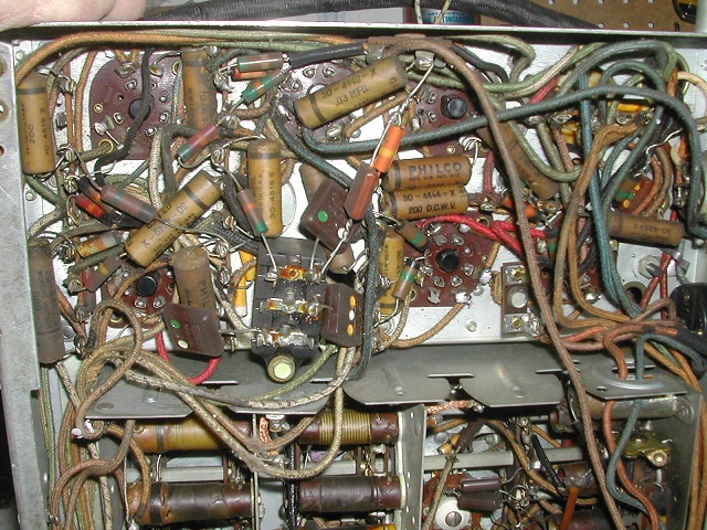
The bakelite blocks in the power supply (two of them) are for a .15uF cap across one of the filter chokes and the second one is for AC line caps to ground (0.015uF). I believe the bakelite block with the 10KC coil is in the chassis which I haven't touched yet. Here is a photo of the chassis underside showing (I think) that bakelite block.

I also think someone installed a cable and box on the chassis for a phonograph plugin attachment. There is a switch to go between phono and radio .

Posts: 133
Threads: 27
Joined: Aug 2006
City: Roseville,Ca.
Thanks for the pics but mine is different.
Gotta love that Zenith tube shield!
I'm lucky,mine is working great!
Still gotta hook up the tweeters the right way though..
Phil
Posts: 57
Threads: 12
Joined: Feb 2009
City: Prescott AZ
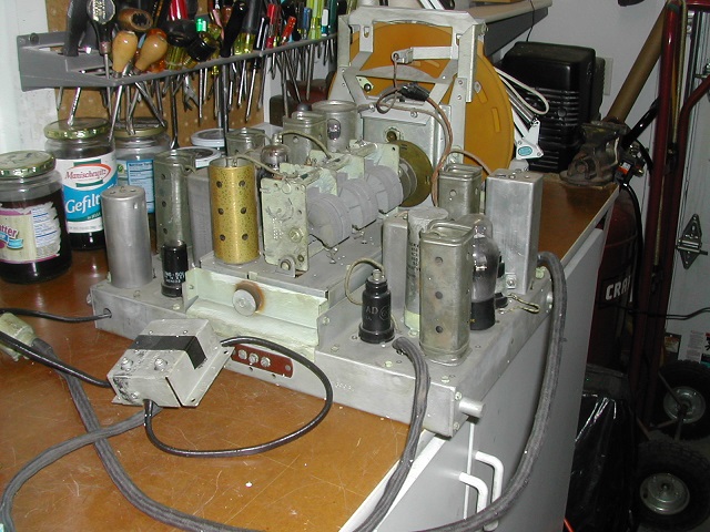
If you look at the top of the chassis you can see some of the seven tube shields AND BASES that have been removed. In most cases metal tubes were put in. That can be fixed and restored over time if and when I get the set working.
Posts: 15,305
Threads: 530
Joined: Oct 2011
City: Jackson, NJ
You could keep the metal tubes if they are properly grounded.
Posts: 1,562
Threads: 56
Joined: Nov 2008
City: Sedona, AZ/Placentia/CA
Mark your right, get it working first. I do believe you have a chassis that might have a few of the tube covers and bases. I gave you a replacement chassis for your rusty one. You may have to dig in to find it. As Mike indicated the metal tubes should be fine for getting it running. No way I would wish to leave them in there long term. That is a nice radio and should look proper. I do have one tube shield I will bring over.
Good luck on it and planning a trip to AZ. City.
Best, Jerry
A friend in need is a pest! Bill Slee ca 1970.
Posts: 236
Threads: 43
Joined: Oct 2010
City: Atlantic Highlands, NJ
I dont remember where the 10kc filter is. It has been a while. Ron has quite a few posts that are helpful if you do a search, especially the tweeter wiring error. Mine is a code 125.
I got my schematic from Chuck, it was very good. I've since bought a hi- res cd with Riders that I use.
I play mine almost every day and the 450v E caps have held up.
Steve
Posts: 13,776
Threads: 580
Joined: Sep 2005
City: Ferdinand
State, Province, Country: Indiana
The bakelite block that contains the 10 KC filter is located in the upper chassis of the 38-690, and is the only bakelite block in the upper chassis.
Leave it alone! Don't touch it! 
--
Ron Ramirez
Ferdinand IN
Posts: 57
Threads: 12
Joined: Feb 2009
City: Prescott AZ
I finished recapping the power supply this morning. Haven't cleaned it or done the cosmetic filling of the holes and hiding the replacement choke in a proper black case (that's all for later on). Surprisingly I didn't have to replace any of the resistors. I hooked the power supply back up to the chassis and slowly powered up on a Variac after running a dim bulb test with the rectifier tubes out of the power supply. This set has so many tubes that my 100W lightbulb was pretty brightly lit so I don't know how valuable the dim bulb test was.
Anyway, after putting the rectifier tubes in place, I slowly powered up the set and today must be my lucky day because the set started to play on AM even with all the original paper caps (and one original electrolytic can in the chassis with a bunch of 1 and 2uF caps). It sounds amazingly good considering the chassis has not been gone through yet. I didn't play it long and kept the voltage at 105-110V input. Now that I know there is nothing major wrong with the set it is a real
impetus to do a careful recapping and check out of the chassis.
In case you haven't guessed I'm about 3 feet off the ground with an ear to ear grin today...
Posts: 1,562
Threads: 56
Joined: Nov 2008
City: Sedona, AZ/Placentia/CA
I can just see that smile Mark. Congratulations just move on slow, find the missing cans and missing shields and bases and work on the powersupply/amp to get it looking great. And you were worried? I have all the faith in your abilities.
A good base line to work from now, you know it works.
Jerry
A friend in need is a pest! Bill Slee ca 1970.
Posts: 57
Threads: 12
Joined: Feb 2009
City: Prescott AZ
Jerry, thanks for all your continued support and help. I'll dig out my Philco parts chassis' after I get everything recapped and cleaned to see how many of the tube shield bases I can salvage and reinstall on this chassis.
Once done, this set will be placed right in the middle of the new radio room so it greets you as soon as you walk in.
Has anyone taken the mechanical tuning mechanism and dial apart for cleaning and lube? That almost intimidates me more than the electronics... Luckily no pot metal in this set so hopefully it's just a matter of finding set screws and the like for disassembly..
Thanks,
Mark


