Posts: 348
Threads: 48
Joined: Oct 2013
City: Tioga, Texas, USA
Here is the updated label for the rotating antenna.
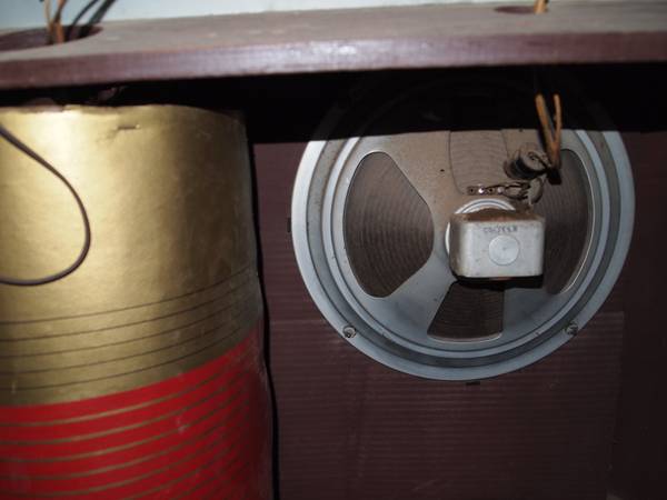
The outer cover is coming along. I think I will do an outer covering of Kraft paper since the OEM paper is self destructing. I have a final internal patch curing right now. The bottom end needs to be finished on the inside in the same way as the top. Once that is done I can put the cover back on the oval wooden forms and staple it down and add the outer covering. That should make a fairly smooth and decent cover that will last a long time. Then I can put the label back on for a finishing touch.
Joe

(This post was last modified: 12-08-2013, 05:12 PM by
Joeztech.)
Posts: 348
Threads: 48
Joined: Oct 2013
City: Tioga, Texas, USA
I found another radio on Craig's list in Dallas area that is a GE model L916 and there is a photograph of a rotating antenna in it that looks suspiciously like the one on the 1940 Philco 40-195/200/201. You can see what looks like electrostatic shield wires underneath the paper outer covering. Philco may have prodded GE to add this feature to compete. I don't have enough data on the unit to be sure.
Joe

Posts: 348
Threads: 48
Joined: Oct 2013
City: Tioga, Texas, USA
Disaster struck! When I tried to slip the outer paper cover back over the wooden structure, the paper ripped open in a couple of places. I conclude that the only way to get this back in working shape is going to be to use some new Kraft paper, perhaps with a piece of posterboard underneath and use the copper strip from the original one. I can use the posterboard as the base and attach the copper strip or tape to one edge, carefully form it around the ends and secure along an overlapping edge. Then I will have to add some bare copper wire to make the shield. The final step will be to wrap the outside with Kraft paper and glue it onto the rest using some spray-on adhesive.
Adding the paper sack reinforcement added too much thickness and the Elmer's glue became too hard. If I had thought, I could have used thinner paper and spray adhesive to begin with - live and learn!
Joe
Posts: 5,205
Threads: 276
Joined: Nov 2012
City: Wilsonville
State, Province, Country: OR
Posts: 348
Threads: 48
Joined: Oct 2013
City: Tioga, Texas, USA
klondike98;
Thanks for that link. I have to wonder if it would survive shipping. An interesting feature of its construction is that the seam is stapled together, while the one from my radio was sewn together. It goes to show how production methods change.
Joe
Posts: 348
Threads: 48
Joined: Oct 2013
City: Tioga, Texas, USA
I made some measurements of the materials used in the construction of this shielded antenna. They are:
Part Number 38-9881
Oval Forms are 4 ½ X 6 7/8 inches and have an approximate 18 3/8 inch circumference.
Paper used is 17 inches tall by 20 inches wide to provide about 1 inch of overlap when formed to fit the oval end pieces. The wires are about no. 29 bare copper wire and there are 65 strands. The wires are spaced approximately ¼ inch apart over a 16 inch axial distance. The spacing is not completely uniform. The wires are parallel from side to side across the 20 inch width dimension.
20 inches X 66 = 1320 inches = 110 ft. for tolerance allowance. The wire could be no. 28AWG or no. 30AWG. The bare copper wire strands are soldered to the copper tape about 1 inch from one end. The other ends of the wires are free. They are not a complete coil as described in the US Patent 2273955. The completed paper/wire assembly is either stapled together or stitched together in the required oval shape. The paper/wire assembly needs to be fit around the oval shape to insure that it slips over the wooden oval forms without damaging the paper as it slides over the wooden oval forms.
I think I will try my hand at constructing one using new paper and wire.
Joe
Posts: 348
Threads: 48
Joined: Oct 2013
City: Tioga, Texas, USA
I ordered some 28AWG enameled magnet wire on Ebay for $8.20 including shipping. Next to acquire some Kraft paper.
Joe


![[-] [-]](https://philcoradio.com/phorum/images/bootbb/collapse.png)


