41-300 Phase 2 restoration
Posts: 42
Threads: 3
Joined: Jan 2026
City: Rochester
State, Province, Country: NY
Over the weekend I installed the fuse and aux in. Success! The phantom voltage is gone too even for whatever reason. Not like the fuse changes the arrangement of the safety caps or anything. And the aux in audio is much cleaner than AM transmitter.
Remaining oddities: It has a bit of hum even with volume down that it didn't before. Nothing awful but noticable. Also despite doing a DPDT switch to send the radio in to ground, switching it to aux only attenuates a strong station, not silences it. Neither are crippling so I can troubleshoot them later.
I ordered some mica caps and an inductor to jury-rig an antenna coupler, though to make it more permanent I'll have to figure out the right size pins to plug into the connector. Those should arrive this week. After that, next phase will be working on the peeling veneer on the center column of the cabinet. I got some Titebond, syringes, and an iron, but details fit better in the other subforum.
I also am thinking I need to align the radio eventually since the dial seems off and I get dual peaks on some things, so I was looking into the details. Seems straightforward when you have the equipment, I just don't presently, so it's not an immediate thing so much as once I have the right test equipment.
1. As I understand, signal generator+oscilloscope is the best way to align but signal generator + voltimeter will work? I could look for a cheap oscilloscope, there are other things I could use it for in the vintage PC sphere, but it hasn't been a priority.
2. Would one of those cheap TinySA spectrum analyzers work as a signal generator for IF alignment? It looks like some people have done it, but has anyone here tried that?
Thanks again, everyone that's given advice on this. It's been a ride the last couple of months, and I think I started on hard mode in terms of vintage radio models to work on, but I'm really feeling the results.
2. What
Posts: 1,797
Threads: 55
Joined: Feb 2015
City: Roseville, MN
I have been using an rf signal generator and a VTVM for over 10 years. Connect a coil of wire to the generator output, sometimes to a tube signal grid through a 0.05 mfd cap. Monitor the AVC with the VTVM because it's more sensitive to signal variations. You can use a DMM instead but it's harder to see variations. Using a scope and sweep generator is for Hams who need to have precise settings. For our purposes, it's a little overkill. Go ahead and use them to get a better feel for how things function.
(This post was last modified: 03-09-2026, 07:48 PM by RodB.)
Posts: 18,427
Threads: 622
Joined: Oct 2011
City: Jackson
State, Province, Country: NJ
I agree, a scope, while nice, is not a necessity, especially when aligning and not troubleshooting.
People who do not drink, do not smoke, do not eat red meat will one day feel really stupid lying there and dying from nothing.
Posts: 2,327
Threads: 23
Joined: Jul 2020
City: Greenlawn
State, Province, Country: NY
Re the hum, check the "lead dress". If the audio wires to the switch are long, use shielded cable. Ground one end of the cable to the chassis. Also, verify the correct wiring of the filter caps.
Re the Phantom voltages, what the others said is correct. The original Philco arrangement was to have the 2 power line bypass caps in series with the center junction connected to chassis. (If you have the chassis grounded to a water pipe (or even to the house wiring), the phantom voltage will be gone. An alternative to the original wiring for these RF Bypass caps is to place one cap across the power line (post power switch) the other cap from the leg without the switch to chassis ground, and to install a polarized plug so that the switch side is Hot and the unswitched side (with the cap to chassis is Neutral. This would eliminate the 60V (low current) on the chassis. However, the noise may either decrease or increase.
"Do Justly, love Mercy and walk humbly with your God"- Micah 6:8
"Let us begin to do good"- St. Francis
Best Regards,
MrFixr55
Posts: 42
Threads: 3
Joined: Jan 2026
City: Rochester
State, Province, Country: NY
I think I might get one of those combo multimeter/basic oscilloscopes eventually either way, but good to know it's not a must. So I'll look for a cheap signal generator perhaps once I feel up to doing alignment.
The wires are a bit long since they cross most of the width of the chassis given the switch is in back and the #46 cap is near the front. Shielding couldn't hurt. Should the ground from the audio jack (or where the radio in gets switched to ground) go through a resistor, or straight to chassis? It seems like every discussion I find about adding in an aux jack suggests different resistor values for left and right for the stereo-to-mono conversion, while some suggest resistors on the ground and some do not.
Parts for the antenna coupler arrived too but I have the chassis out so I can glue some veneer and I took the long wire down since ants were coming in along it when the weather turned nice. I'll get to it eventually.
Posts: 3,186
Threads: 226
Joined: May 2008
City: Omak
State, Province, Country: WA
Hello Red,
Far as combo multimeter/basic oscilloscopes I also thought about getting one.
Veneer work is one task I am not that good at I have few sets that need it to.
Sincerely Richard
Posts: 18,427
Threads: 622
Joined: Oct 2011
City: Jackson
State, Province, Country: NJ
Shielding only works when it is connected directly to chassis.
The idea is for it to be at the common/GND potential and to be the drain for the stray/return currents.
Otherwise it will hurt more than it will help.
People who do not drink, do not smoke, do not eat red meat will one day feel really stupid lying there and dying from nothing.
Posts: 42
Threads: 3
Joined: Jan 2026
City: Rochester
State, Province, Country: NY
Glued down the peeled veneer, not super aligned but it's hide glue so i can revisit later maybe.. Old English was magic on the scuffs. Reassembled and about ready to place in the downstairs hall until I'm ready to tackle alignment .
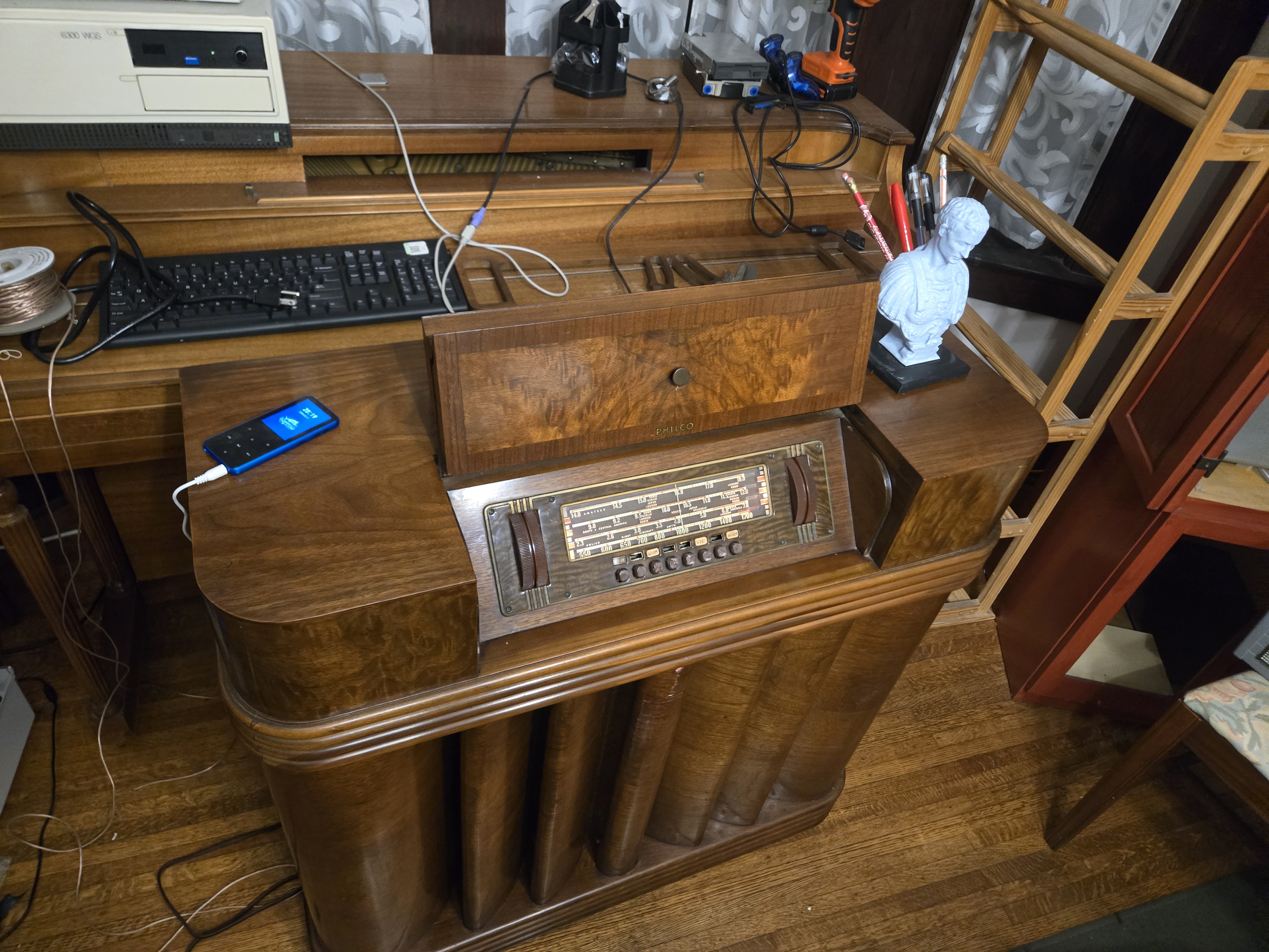
I still need to test the antenna, but after that I'm going to work on setting up a more 90s stereo for upstairs.
Posts: 2,327
Threads: 23
Joined: Jul 2020
City: Greenlawn
State, Province, Country: NY
Nice job, Red! A rather handsome set!
"Do Justly, love Mercy and walk humbly with your God"- Micah 6:8
"Let us begin to do good"- St. Francis
Best Regards,
MrFixr55
Posts: 3,186
Threads: 226
Joined: May 2008
City: Omak
State, Province, Country: WA
Hello Red,
Wow, you’ve really outdone yourself on this one. Nice job!
Sincerely Richard
Posts: 4,832
Threads: 437
Joined: Jun 2011
City: Boston
State, Province, Country: Massachusetts
Very fine job, nice. Paul
Tubetalk1
Posts: 18,427
Threads: 622
Joined: Oct 2011
City: Jackson
State, Province, Country: NJ
Very good looking radio.
Matches the piano too!
People who do not drink, do not smoke, do not eat red meat will one day feel really stupid lying there and dying from nothing.
Users browsing this thread: 1 Guest(s)
|
|
Recent Posts
|
|
Philco P45-6365 Universal Transformer Instruction Manual
|
| Can anyone guide me to where this may be found?GRG — 03:00 PM |
|
54C Complete Teardown/Rebuild
|
| I don't think that I have encountered a 12Z3 before, curious how it uses one of those but includes a #43, which is a 25 ...Arran — 02:17 PM |
|
HiFi (Chifi) tube amp build - but my own design.
|
| It's the other forum. I'm also in DIY, but mostly read there. Honestly, I kinda jumped into this without much thought to...TV MAN — 10:43 AM |
|
Philco 71 Code 125
|
| Hello,
I am in need of a schematic for this radio. Mine has the three separate circular tube shields and a shadow me...dconant — 08:06 AM |
|
Stromberg Carlson 1500 Squeal
|
| And life just keeps getting more complicated.dconant — 07:57 AM |
|
54C Complete Teardown/Rebuild
|
| Hello Roy,
here is this one
sincerely Richardradiorich — 12:45 AM |
|
54C Complete Teardown/Rebuild
|
| Richard,
Had grabbed it already but thank you just the same. I find myself wanting to find some way to block out the...glyphmon — 12:03 AM |
|
54C Complete Teardown/Rebuild
|
| Hello roy,
here is a link to the schematic .
Sincerely Richardradiorich — 11:54 PM |
|
54C Complete Teardown/Rebuild
|
| Richard,
The Silvertone 2014 also is a transformerless set, so I am incorporating a 1:1 600 ohm audio isolation transfo...glyphmon — 11:37 PM |
|
Preliminary work on wife's Silvertone 2014
|
| Did an alignment today which was interesting. IF alignment went great, almost all was already spot-on. Adjusting on th...glyphmon — 11:35 PM |
|
Who's Online
|
There are currently 1776 online users. [Complete List]
» 2 Member(s) | 1774 Guest(s)
|
|
|

|
 
|









