Beginning a 37-620 Restoration
Posts: 172
Threads: 10
Joined: Mar 2026
City: Franklin
State, Province, Country: Maine
Richard,
Thanks for the suggestion. Unfortunately, there's not much else in this circuit, though one component is the compensator (37) which, in the absence of any other explanation I suppose could be problematic. I defer to the experience of others if that could cause these wildly fluctuating voltages.
I think the 6Q7 was the culprit on the noise. I swapped in a different one and the sound went away. Came back when back to original, so I did try heating the grid cap of the original until it smelled warm, and tried it back in place. So far, random sound has not reappeared so +1 win for Google and one problem hopefully done with. Now it's just a matter of figuring out our voltage problem around the 2nd IF transformer.
If I get that squared away, I should be able to even think about doing the alignment I wanted to try at the end of April.
Best wishes,
Roy
Posts: 172
Threads: 10
Joined: Mar 2026
City: Franklin
State, Province, Country: Maine
MrFixr55,
Well, for better or worse, I've extracted the 2nd IF transformer from the radio. Thankfully, it wasn't buried by everything else in that section. </sarcasm> It doesn't "look" bad - it does look old. Connecting the multimeter, I got right around 11 ohms at first which matches, BUT, the longer I leave it connected, the more it keeps creeping upward, just with the multimeter attached. It's currently sitting at 19.7 ohms after about 5 minutes. If it can drift like that with just what little current the multimeter is throwing at it, is it likely to be the case that this would be the culprit in the poor voltages reaching the plate of the 6K7?
I can post a picture if it's helpful, but not sure that it would be at this juncture. Obviously there's continuity, but that's also clearly not the problem.
19.8 ohms as I'm finishing writing this. It doesn't look particularly like a repairable part, so I'm guessing replacement or nothing?
Edit as of a few minutes later. Failing to see a downside, I heated up the solder on the lugs for the primary winding and reattached one of the wires to the rest of the radio after it fell out. Following that reattachment, I tested continuity again and at one point got a solid 10.5 ohms which after several minutes only ever barely touched 10.6. Reassembling the can was a joy but now have it back together and physically attached to the chassis. I checked continuity again and though I can't get 10.5 ohms, I still have continuity and in the neighborhood of 11.3 - 11.7 ohms depending on how good my connection on the wire is.
I'll post an update once I get everything soldered back together, especially if the magic smoke doesn't come out.
Best wishes,
Roy
(This post was last modified: 10-04-2026, 08:18 PM by glyphmon.)
Posts: 2,327
Threads: 23
Joined: Jul 2020
City: Greenlawn
State, Province, Country: NY
That's right Roy, smoke is what makes many mechanical, electrical and electronic things work. When you let the smoke out, they stop working. Hopefully, when you get around to powering the radio up you will be rewarded with mamy stations and no noise (other than what is normally received with all the electronic pollution from LEDs, CFLs, switching power supplies, cell phones, WiFi, the Internet of Things, etc.
"Do Justly, love Mercy and walk humbly with your God"- Micah 6:8
"Let us begin to do good"- St. Francis
Best Regards,
MrFixr55
Posts: 3,186
Threads: 226
Joined: May 2008
City: Omak
State, Province, Country: WA
Hello mr fixxr,
Yes, especially if you are working on an English car with Lucas wiring, keeping the smoke in is mandatory.
Richard
Posts: 172
Threads: 10
Joined: Mar 2026
City: Franklin
State, Province, Country: Maine
Okay, managed to wire it back together despite a counting error on my part in disassembly. It didn't look right and so I'm glad I double-checked, elsewise, there may have been an opportunity for venting of the magic smoke.
But I'm pleased to report that all the magic smoke is still contained within and it powered up as one would expect. Of course, before I was consistently able to receive the local station during the daytime, and I could hear multiple stations at night. It is still receiving, though poorly, and due to it being night, I can tell that there are several stations it's trying to tune in. I suspect the fix(es) made to the transformer may have made an alignment more necessary as now, I hear much more the "heterodyning" noise as I've heard it described, and it seems to be overlapping with the stations, instead of "surrounding" them. The stations are relatively quiet where I can get the heterodyning sound to be gone.
But, as I said, I think that may be able to be addressed with an alignment. The fact is, the stations are there, and I now get a solid, reasonably stable 249V - 250V at the IF 6K7 plate.
So here's a theory: that this transformer may have been bad for a while - even since the last time the radio was aligned, since correcting the 2nd IF transformer solder joints (necessary to fix the voltage on the 6K7) knocks the radio somewhat out of alignment. Make sense or should I save the theorizing until I've learned the craft some more?
As I said, the radio played before, but I have no knowledge of what the voltages looked like before I started messing with it, so perhaps it was calibrated to work "properly" in that sub-optimal state?
In any case, I wash my hands of it for tonight. The next day I work on it, I will take a final set of readings of voltages, just to get a sense for the whole picture and then potentially try to align it, which I hope brings back at least the level of quality that I had before. With any luck, maybe it will be better.
I did find a discrepancy between the wiring in the radio and the schematics, though, which I will run by you, simply because I don't believe this is a mistake in my work since the beginning:
As presently wired, and like I said, I believe since before I started working on this radio, pin 5 on the IF 6K7 (suppressor grid) is not connected as drawn on the schematics to Resistor 55, and by extension to the bias resistor, but instead to pin 1 on the 6A8 (shield) and also to ground. That 6A8, pin 1 connection appears to be the path to ground for the 6A8 heater as well. Now, I did unsolder the wire coming from the 6A8, pin 1 in the process of removing the tuning sub-chassis, and I could potentially have been accused of mistakenly connecting it to the wrong pin on the 6K7 when putting it back together, but I don't believe I would have made such an egregious error as to have soldered it back to a tube instead of to either the terminal strip or a grounding tab. I certainly wouldn't have removed and reattached the wire from the ground tab to pin 5 on the 6K7 that didn't need removing, hence why I'm pretty sure this hasn't moved. Maybe it's a change? Maybe it's an incorrect schematic? Whatever the reason, it definitely didn't happen tonight.
In any case, the radio is still in as playable a state as it has been (excepting alignment), and not sure what this kind of discrepancy would yield as compared to being wired as shown in the schematic. Thoughts? Should I attempt to rewire this connection?
Thank you very much, MrFixr55, for keeping me looking in the correct direction for troubleshooting the voltages. I wish I hadn't had to get into the transformer, but I'm glad doing so yielded this much result, at least.
Best wishes,
Roy
(This post was last modified: 10-04-2026, 11:11 PM by glyphmon.)
Posts: 172
Threads: 10
Joined: Mar 2026
City: Franklin
State, Province, Country: Maine
Okay, another mystery has opened up, and I'm sure this one has to be my fault.
A fresh set of voltage readings:
6F6G
Plate: 240V (240V)
Screen Grid: 259V (250V)
RF 6K7G
Plate: 254V (245V)
Screen Grid: 76V (70V)
Suppressor Grid: -3.16V (?)
6A8G
Plate: 261V (245V)
Pin 4 (grids 3 and 5): 75V (70V)
Osc Control Grid: 192V (?) ***
Osc Plate: 262V (150V) ***
6Q7G
Plate: 182V (150V)
IF 6K7G
Plate: 250V (250V)
Screen Grid: 75V (70V)
Suppressor Grid: 0V (?)
So by comparison, most of these are spot on, but now, for some reason, the oscillator section of the 6A8 is completely out of whack.
Now, the socket voltage diagram doesn't say what value the Oscillator Control Grid (pin 5) should have, but it previously was a negative, approximately -10V. Tracing the path through the schematic, it looks like it comes up ultimately out of the tuning subchassis and connects at the junctions of Resistors 17, 29, and 64, where I usually have around 200V. So maybe this is correct and I should have worried about the -10V previously? The 6A8 data sheet says pin 5 is grid 1, which doesn't get spoken to by number in the sheet that I've been using, so I can't even really tell which voltage they prescribe. Maybe they don't, and maybe I'm worried over nothing.
In any case, the Oscillator Plate (pin 6) voltage being 262V where 150V is expected (at least according to the socket voltage diagram), seems extreme, but that comes through the 1st IF transformer primary, and from there, Resistor 33, where I'm having about 262V, down from 264V before the resistor, so I don't know how to take that value either. Bad diagram? The data sheet says this is grid 2 - the anode grid, which is supposed to have a max of 200V, so that worries me.
Aside from that, the plate on the 6Q7 is still high, but that hasn't changed.
Thoughts? Am I worrying too much? The voltages are now at least pretty steady though there may be a +/- 1V here and there.
I'm not sure how the voltages on the 6A8 could have changed so much from just what I did with the 2nd IF transformer (removing, fixing, reinstalling). I think the only thing that was adjacent was the connection to R33 but there's no short there, they are still separated. I would think if I had something installed wrong, the radio would perform much worse and I'd see weird voltages in more than just one place.
No alignment tonight - figure I'd pick your brain on these readings before I commit. I also don't want to fry the 6A8 by running it with too-high voltage, certainly my a margin of greater than 20% over its advertised maximum.
Best wishes,
Roy
(This post was last modified: 10-05-2026, 10:10 PM by glyphmon.)
Posts: 2,327
Threads: 23
Joined: Jul 2020
City: Greenlawn
State, Province, Country: NY
Hi Roy,
First question, does the radio play any better than it did or is it dead? I am thinking that based on your voltage readings, especially for the Oscillator grid, that the radio is dead.
Looking at the schematic, the 6A8 plate-grid (G2, which serves at the oscillator plate) does not come from the same line that B+ for the Output tube, RF and IF tubes or even the main plate of the 6A8. It comes from the rectifier output before the field coil, through a voltage divider consisting of Resistors 64 (9KOhm), 17 (51KOhm) and 16 (20KOhm). The voltage at the junction of Resistors 17 (20KOhm) and 64, and Cap 18 should be less than or equal to about 280V. These resistors are likely good, as the screen voltage for the 2 6K7s and 6A8 are derived from the junction of R16 and R17, and these are substantially in spec (75V vs 70V). The voltage is further stepped down through a 10K resistor before supplying the "plate grid" (Oscillator plate) of the 6A8 through the primaries of the Oscillator coil.
The Oscillator grid (G1) is connected to whatever secondary is selected. the other leg of the secondary selected is grounded through a 32K resisttor.
Troubleshoot by powering off, pulling the 6A8 and verifying that resistance between Pin 5 and Chassis Ground is approximately 32K Ohms no matter what position the band switch is in. Troubleshoot the circuit if this is not the case.
Hope this helps.
"Do Justly, love Mercy and walk humbly with your God"- Micah 6:8
"Let us begin to do good"- St. Francis
Best Regards,
MrFixr55
Posts: 172
Threads: 10
Joined: Mar 2026
City: Franklin
State, Province, Country: Maine
MrFixr55,
Neither, it's definitely not dead, but the performance is worse. It is picking up signals, and if I don't really mess with it too much at first, it can reasonably clearly deliver the local station. However, there is pronounced sound when tuning around stations, a "whine" that increases or decreases in pitch, usually depending on how closely we are tuned into the station. This is really overpowering the signal right now. Where that noise goes away, almost like a zero-beat, there's often a faint bass-y remnant of the radio signal.
Best wishes,
Roy
Posts: 3,186
Threads: 226
Joined: May 2008
City: Omak
State, Province, Country: WA
Hello Roy,
what you describe is classic heterodyne beating. The radio is generating an unwanted signal that mixes with the station and produces an audible whistle.
If you ajusted the If cans adjusted recently, they may be off frequency.
The Philco 37-620 uses a 470 kHz IF. If one IF transformer is significantly misaligned, the set can become unstable and produce whistles and squeals around stations.
sincerely Richard
Posts: 172
Threads: 10
Joined: Mar 2026
City: Franklin
State, Province, Country: Maine
Richard,
Thanks for confirming. I haven't adjusted the alignment directly, recently, but I did work on the 2nd IF transformer to fix the voltage issue on the IF 6K7. I suspect it will need an alignment performed as a result. I also suspect that in the reassembly I may have created a short somewhere, somehow, that is supplying different, higher voltages into the tuning section, in particular, the oscillator section, and sending the voltages on the oscillator portions of the 6A8 through the roof.
After testing the 6A8 tube in case of any miraculous shorts (it didn't have one, according to my tester, at least), I think my next step is to try cutting the proper connection to power from this section (red line in the lower left of image) and see if I find there's still power/continuity from elsewhere, outside of this circuit, and do process of elimination from there. There shouldn't be, at least according to my reading of the schematic, any way for power to get into the oscillator plate except through the light green highlighted path, so if it is, then I've probably erred somewhere in the last 36 hours.
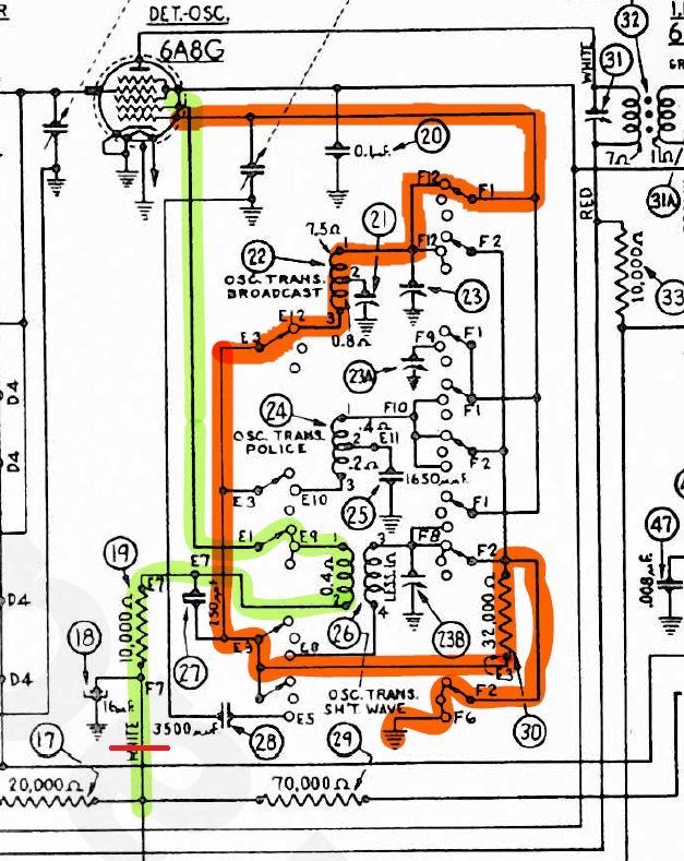
Best wishes,
Roy
Posts: 2,327
Threads: 23
Joined: Jul 2020
City: Greenlawn
State, Province, Country: NY
Hi Roy,
I added to my previous post. Sorry, I fell asleep while working on it. My notes center on the oscillator grid circuit, as the voltage you reported is incompatible with the radio functioning. Do you have a signal generator or signal tracer? These may be needed to further troubleshoot.
Read my previous post, also power up without the 6A8 out of circuit. There should be no noise other than very slight hum and hiss.
"Do Justly, love Mercy and walk humbly with your God"- Micah 6:8
"Let us begin to do good"- St. Francis
Best Regards,
MrFixr55
Posts: 1,135
Threads: 54
Joined: Feb 2013
City: Shenandoah,
State, Province, Country: Pennsylvania
Hi Roy, just for giggles, if you have a different voltmeter, try using that. I say this because I’ve seen meters go nuts with unexpectedly high readings when used around RF/oscillator frequencies. Some meters don’t handle those high frequencies well. Since your radio still receives stations, the oscillator has to be working so having 192v on the osc. Control grid instead of the -10v really can’t be. Also, some of the voltages you are getting vs what the service info calls for, aren’t terrible. Take into account that the published voltages were taken by Philco back in 1937 with a meter most likely of lower sensitivity…ohms/volt… than the meter you are probably using so the load on the circuits are significantly different. Certainly measuring 260v where 150v is expected is a concern.
Ron
Bendix 0626. RCA T64 Philco 20B
Philco 41-250. Philco49-500
GE 201. Philco 39-25
Motorola 61X13. Philco 46-420 Crosley 52TQ
Philco 37-116. Philco 70
AK 35 Philco 46-350
Philco 620B. Zenith Transoceanic B-600
Philco 60B. Majestic 50
Philco 52-944. AK 84
Posts: 2,327
Threads: 23
Joined: Jul 2020
City: Greenlawn
State, Province, Country: NY
Hi Roy, and other Gents,
Sorry, I am not on top of everyone else's posts, as I have been on the computer only at night and between breaks from working on my car (had to drop the gas tank on my 2003 taurus to investigate a gas smell and to replace the fuel pump. (I added a through floor access to the fuel pump in case I ever have to service it again as at 71, having arthritis and being morbidly obese, dropping the gas tank was not fun.
Roy, you did a GREAT job of tracing the oscillator grid and plate circuits. I started to do so off line, then fell asleep. This is why I find it incredulous that the 6A8 stage is functional with the voltages measured. I think that RadioRich is correct.
BTW, Richard, you are absolutely correct re English cars with Lucas electrics. They called Lucas the "Prince of Darkness". If you owned a British car, you needed to have a manual transmission a good steep hill to park the car on and plenty of high power flashlights. The family owned a 1970 Mercury Capri with the 1.6L "Kent" crossflow headed engine, a great little engine. These were imported from Germany and sold in Europe as the Ford Capri. They were built in either England or Germany, but the German car is the one imported to the US. The body electrics were Hella. If you had the 2.0 or 2.8L German Koln (Cologne) engines, you got a Bosch alternator and starter. However, if you ordered the 1.6L British Kent engine, you got the Lucas alternator and starter. And that alternator was total garbage.
"Do Justly, love Mercy and walk humbly with your God"- Micah 6:8
"Let us begin to do good"- St. Francis
Best Regards,
MrFixr55
Posts: 172
Threads: 10
Joined: Mar 2026
City: Franklin
State, Province, Country: Maine
Thank you everyone for chiming in.
First, to MrFixr55's suggestion of measuring the resistance from pin 5 on the 6A8 to chassis ground with the tube removed, it tests at 34K ohms. When I replaced this resistor, I couldn't get a 32K, so I went with 33K instead, so this feels like close to where we should be - certainly within 20%, though higher than I would expect from the path to ground. And don't be sorry for falling asleep while thinking about my problem. I needed to sleep two nights to get the ambition back to look in the darn thing again.
Second, because it was fairly non-invasive, I snipped the wire running from the junction of R17 and R29, which itself runs to F7 on the band switch, and tested for continuity as best I could (20M ohms setting) between the oscillator section side of that wire, and every terminal on the terminal strip, the pins on the 6Q7 and IF 6K7, and at the junctions of the electrolytics up adjacent to the field coil. The good news, I suppose, is that I couldn't find anything other than infinite resistance, so if there's short, there isn't a strong one.
Would it be problematic to power the radio on briefly to see if stronger current is successful in finding a path? Without the oscillator section powered, it simply just shouldn't work, at all, right? And if not, then we know, whatever is coming in is coming in through that snipped wire, and it can't be more than what the voltage is at that junction, and therefore, is just a wonky reading related to the meter used to do the measurements? I haven't tried powering it on without the 6A8 installed yet, but imagine the result would not be too different.
Does it make sense that if the radio is simply terribly out of alignment now, that that could be introducing the weird readings with this meter, even though it had relatively nominal readings for the oscillator before?
I know there has been discussion about how to simulate older equipment, i.e., 1000 ohms per volt meter, with modern equipment. Would that be worth trying to see if that has any effect? I do have a Heathkit IM-11 VTVM, but not sure if that would be any better at this particular measurement. Goodness knows the probe certainly won't fit where I need to stick it to reach the pins.
I do have a signal generator, but no signal tracer as yet. I think though, with the above diagnostics, I can assuage my concerns about the potential for a short.
Based on the outcome of these next steps, I guess the next thing I should do is try an alignment and see what that gets me. Maybe everything falls back into place.
When this is all said and done, I'd be curious to hear people's opinions on the design of at least this chassis, and, I suspect, any Philco utilizing unit construction vs designs from other manufacturers. For example, the RCA 6K3 that I worked on had the same essential band ranges, a three-band switch, a two-gang tuning condenser, but when you look at the schematics, and indeed, inside the chassis as a whole, it is far simpler and less-cramped than this 37-620. I'm sure some will argue that by separating all the different coils and transformers out, and having the extra gang, and every other difference, that maybe it will have resulted in a higher quality product. But in your experience, did it really? Was it noticeable? Or did it simply make a charlie-foxtrot out of something that could have been much simpler?
Best wishes,
Roy
Posts: 172
Threads: 10
Joined: Mar 2026
City: Franklin
State, Province, Country: Maine
Thank you all - Mike, MrFixr55, Rod, Richard, Dale, Arran, and I'm sure others I'm not immediately remembering for the assistance in getting this radio to this point.
I tested my theories today and found the oscillator without power with that wire severed so conclude that as was suggested, the voltage readings are not reliable with modern equipment on the 6A8 oscillator pins. So I did the best alignment I could without a separate vernier drive for the shortwave band, so we'll see how it goes. I'm going to try not to move it too much from AM anyway, given the touchy nature of the band switch.
Here's a recording of it playing while tuned into the AM transmitter nearby. I think the fidelity is reasonable given its age and prior repairs to the cone and lack of tone control.
https://youtu.be/ob20VDoIhtY
Still curious about people's opinions on the design of at least this chassis, and, I suspect, any Philco utilizing unit construction vs designs from other manufacturers. Did these more complicated designs pay off in terms of output/reception quality? Obviously they were more economical to make and more difficult to service.
Thank you all again for your expertise, patience, and time. Catch you on the next radio.
Best wishes,
Roy
Users browsing this thread: 24 Guest(s)
|
|
Recent Posts
|
|
Philco P45-6365 Universal Transformer Instruction Manual
|
| Can anyone guide me to where this may be found?GRG — 03:00 PM |
|
54C Complete Teardown/Rebuild
|
| I don't think that I have encountered a 12Z3 before, curious how it uses one of those but includes a #43, which is a 25 ...Arran — 02:17 PM |
|
HiFi (Chifi) tube amp build - but my own design.
|
| It's the other forum. I'm also in DIY, but mostly read there. Honestly, I kinda jumped into this without much thought to...TV MAN — 10:43 AM |
|
Philco 71 Code 125
|
| Hello,
I am in need of a schematic for this radio. Mine has the three separate circular tube shields and a shadow me...dconant — 08:06 AM |
|
Stromberg Carlson 1500 Squeal
|
| And life just keeps getting more complicated.dconant — 07:57 AM |
|
54C Complete Teardown/Rebuild
|
| Hello Roy,
here is this one
sincerely Richardradiorich — 12:45 AM |
|
54C Complete Teardown/Rebuild
|
| Richard,
Had grabbed it already but thank you just the same. I find myself wanting to find some way to block out the...glyphmon — 12:03 AM |
|
54C Complete Teardown/Rebuild
|
| Hello roy,
here is a link to the schematic .
Sincerely Richardradiorich — 11:54 PM |
|
54C Complete Teardown/Rebuild
|
| Richard,
The Silvertone 2014 also is a transformerless set, so I am incorporating a 1:1 600 ohm audio isolation transfo...glyphmon — 11:37 PM |
|
Preliminary work on wife's Silvertone 2014
|
| Did an alignment today which was interesting. IF alignment went great, almost all was already spot-on. Adjusting on th...glyphmon — 11:35 PM |
|
Who's Online
|
There are currently 1300 online users. [Complete List]
» 1 Member(s) | 1299 Guest(s)
|
|
|

|
 
|








