Posts: 16,481
Threads: 573
Joined: Oct 2011
City: Jackson
State, Province, Country: NJ
To ditto that, in my most recent project, Zenit with the old FM, some caps that are parts of FM circuitry, while being tubulars, are in fact low value ceramic types (20-50pF range); they were exactly of the value declared and were left alone.
People who do not drink, do not smoke, do not eat red meat will one day feel really stupid lying there and dying from nothing.
Posts: 182
Threads: 5
Joined: Feb 2017
City: Cedar Rapids Iowa
(03-30-2017, 12:08 PM)Mondial Wrote: Rich, be careful about replacing caps in the tuning front end chassis. There are many caps there that should be left alone, including the precision micas in the tuned circuits.
The only caps to change there are the waxed paper bypass caps.
Thanks Mondial! Yes, I am aware that the mica caps shouldn't be replaced. I'm checking them as I go and so far all are real close to the specified value. So the only caps I've replaced are the paper and electrolytics.
Rich
Posts: 1,114
Threads: 14
Joined: Feb 2013
City: Irvington, NY
Also, with respect to the power transformer, the 6.3V winding for the tube filaments will read almost a dead short, so if this is the winding you are referring to its not a problem.
Posts: 182
Threads: 5
Joined: Feb 2017
City: Cedar Rapids Iowa
(03-30-2017, 12:23 PM)Mondial Wrote: Also, with respect to the power transformer, the 6.3V winding for the tube filaments will read almost a dead short, so if this is the winding you are referring to its not a problem.
Ah, good...thanks! I'll check it out. But if I end up using that transformer I'll have to figure out a way to mount it and will have to mount a second 12v CT transformer for the heater circuit. I'd really like to find the right one.
Rich
Posts: 1,114
Threads: 14
Joined: Feb 2013
City: Irvington, NY
As I understand it, your replacement transformer has a 6.3V winding for the tube heaters (filaments), but no 5V winding for the rectifier 5Y3GT. Is this correct? How did you have the present transformer connected to the heaters when the radio was working?
If you can't find a suitable transformer, you can use your present one by replacing the rectifier tube with silicon rectifier diodes and leaving the 5Y3GT tube with its socket wiring unconnected. It won't light up but will at least look original
Posts: 182
Threads: 5
Joined: Feb 2017
City: Cedar Rapids Iowa
(03-30-2017, 01:10 PM)Mondial Wrote: As I understand it, your replacement transformer has a 6.3V winding for the tube heaters (filaments), but no 5V winding for the rectifier 5Y3GT. Is this correct? How did you have the present transformer connected to the heaters when the radio was working?
If you can't find a suitable transformer, you can use your present one by replacing the rectifier tube with silicon rectifier diodes and leaving the 5Y3GT tube with its socket wiring unconnected. It won't light up but will at least look original
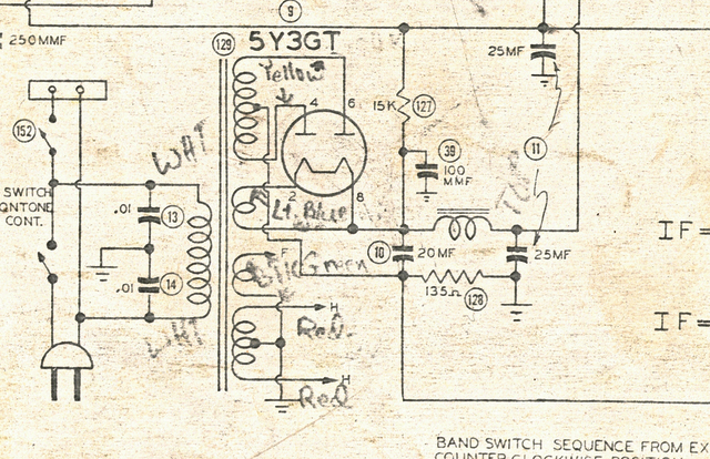
Based on the way it was wired, it was missing the 2nd 6v (12v ct) secondary marked H (Heater?) on the schematic. The way I got around that 45 years ago when I replaced the transformer was to use the existing 6v secondary to drive the heater circuit and ground the other side of the heater. I also had replaced the rectifier tube with solid state diodes. I'd really like to put this back to the way it's supposed to be but will consider all options.
Thanks!
Rich
(This post was last modified: 03-30-2017, 02:58 PM by criageek.
Edit Reason: Incorrect facts
)
Posts: 1,114
Threads: 14
Joined: Feb 2013
City: Irvington, NY
OK, but both windings of the original Philco transformer are 6.3 V. There is no 12.6 V winding. The center tapped winding is 3.15 V each side of the tap. Otherwise, with a 12.6 V winding you would be applying 12 V to the 6 V heaters.
That one winding is only center tap grounded for hum reduction, feeding the low level audio tubes and FM detector. Grounding one side of an untapped winding for the heater supply, and feeding all the heaters is OK, but you may have a bit more hum.
Posts: 182
Threads: 5
Joined: Feb 2017
City: Cedar Rapids Iowa
That's some great info Mondial! Thank you!
Rich
Posts: 182
Threads: 5
Joined: Feb 2017
City: Cedar Rapids Iowa
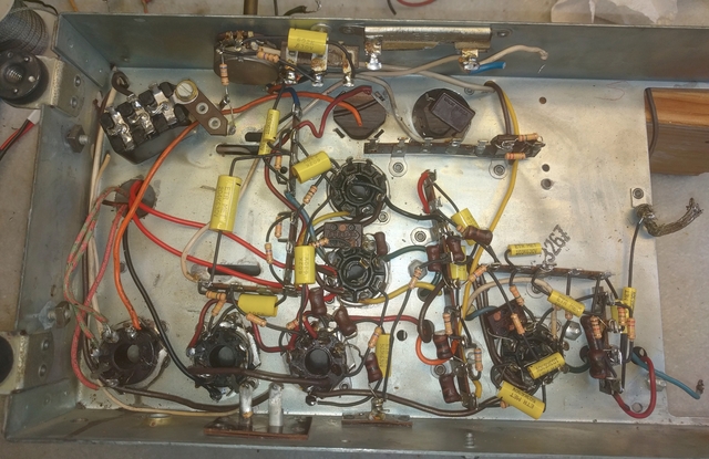
Today's progress. It's amazing how much cleaner it looks. Still need to rebuild the caps/resistors on the terminal strip toward the top, and then re-install the electrolytic cans, but then the main chassis will be done. Well, other than some wiring. Now the fun part...the caps in the tuner sub-chassis  I'm considering taking the mounting nut off the band switch to see if it gains me some access to the 3 caps in there that need to be replaced, but concerned about doing some damage. Thoughts?
Rich
Posts: 182
Threads: 5
Joined: Feb 2017
City: Cedar Rapids Iowa
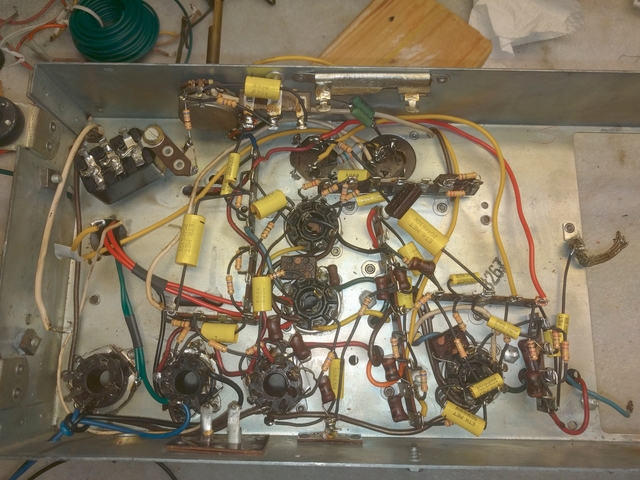
More progress. I have 2 more caps to re-install. Just waiting until all connections that will be below them have been made. I've been putting off working on the tuner sub-chassis as long as I can, but it looks like I'm going to have to attack that in the next day or two.
Rich
Posts: 182
Threads: 5
Joined: Feb 2017
City: Cedar Rapids Iowa
Ok, I finally did the tuner sub-chassis today. It was difficult, but not as bad as I expected.
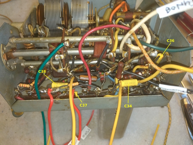
I really HATE leaving old components in place, but one of the caps was really buried and I couldn't even SEE the ground lead, let alone get cutters or a soldering iron on it. So after measuring it for my documentation I clipped the other lead completely off and stuffed it down into the chassis as far as I could and it'll have to stay there.
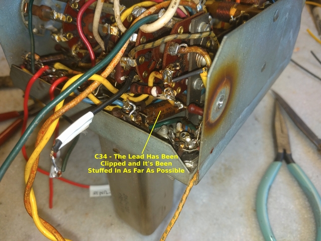
Now I need to do some cleanup on the top side of the tuner sub-chassis, finish attaching wires for the power transformer, wire in the output transformer and the speaker connector, then figure out what I'm going to do about the power transformer. Plus I need to order a few parts. I had some brain fade and ordered a 0.47uF electrolytic instead of a 4.7uF, plus there are a couple of mica caps that are missing from the circuit. I'm pretty sure I removed one of them when I worked on this set many years ago and never replaced. The others appear to have never been in the circuit so don't know if I'll put them in.
Rich
Posts: 641
Threads: 48
Joined: Mar 2017
City: Gap Mills Wv 24941
good job so far,, i have been reviewing this thread , lots of hard work.
Posts: 182
Threads: 5
Joined: Feb 2017
City: Cedar Rapids Iowa
Today I want to share my process for documenting my progress. Perhaps it will trigger a discussion where others can share their methodology and help anyone that struggles with such things.
First and foremost, I've taken tons of pictures...263 so far. On most I've made comments to help me remember pertinent info. I'm a Linux (Ubuntu) user so I use gThumb to crop, resize, and enhance photos. Then I use Gimp to make comments or other markings.
I've also made hand drawings to keep track of what should be attached where. I like to remove all parts from a terminal, clean it up, then re-attach them. The drawings help a great deal since everything is so intertwined and it's difficult to see what's on each terminal in a photo.
I created 3 spreadsheets (I use Libre Office), one for caps, one for resistors, and one for mica caps. Here is a sample of the caps spreadsheet:
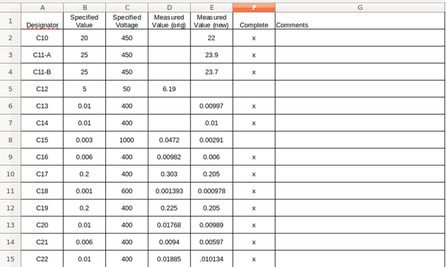
For each part I take a reading of the value for the current part, and if I replace it I document the value for the new part. Then when the replacement is complete I put an 'x' in the complete column. The spreadsheet for the mica caps is purely for info, although if I come across one that is way out of tolerance I'll replace it. Here's a sample of that spreadsheet showing how I use the comments column:
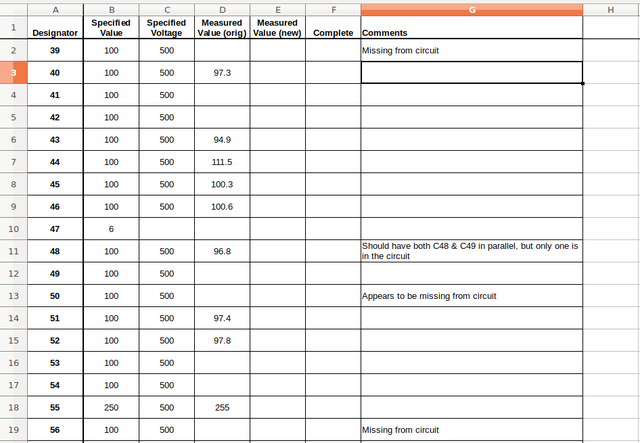
I hope this helps someone and look forward to seeing how others do it 
Rich
Posts: 182
Threads: 5
Joined: Feb 2017
City: Cedar Rapids Iowa
Today I have a couple of safety questions.
When I replaced the line filter caps in the bakelite container I used the same .01uF caps used elsewhere in the circuit. The part numbers that are called out in the Sam's Photofact are the same. But I've seen posts that suggest that you should use 'Safety Caps' ('Y' rated I think?). Should I pull those out and put in safety caps, or will they be ok?
Now that I have all the power transformer wires connected
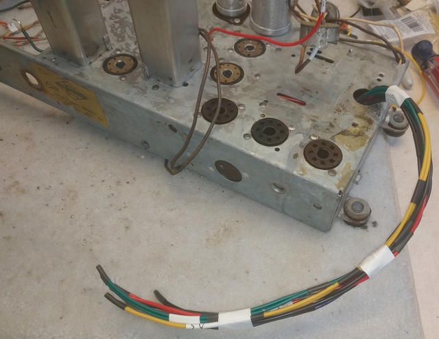
I decided I should check to see if the wire I'm using is heavy enough. I'm using 18ga stranded. According to the chart on this page: http://www.engineeringtoolbox.com/wire-g...d_419.html it should be able to handle 4.9 amps. The Sam's info says that the one of the 6v secondaries is rated at 2.9A and the 5v secondary is rated at 1.8A. Will my 18ga wire be heavy enough, or should I swap it out for 16ga?
Thanks
Rich
Posts: 641
Threads: 48
Joined: Mar 2017
City: Gap Mills Wv 24941
craig,
go to lowes, electrical section
purchase an "ugly's".
its a yellow book with read binder, fits in your back pocket.
its the NEC in small format.
Google NEC table 310.16, takes you down to 18awg.
always use "in raceway" or cable tray/wireway tables for doing things like this. you are not a "free air" application.
your wire you chose had an insulation data sheet or it says info on the wire itself.
If you wire has no information on it, its not UL or even UR.
You said "stranded" wire....
stranded actually means a single hard to bend conductor (like on my xfrmr these are all stranded / single)
Stranded is also where you have several stiff wires inside the same jacket,, like household Romex.
anytime "stranded" is used, it means a single or multiple hard to bend conductors.
Most of the time this type of "stranded wire is used in THHN/THWN applications.
"flex" or most correctly stated is RHH/RHW is multiple iddy biddy tiny hairs of copper.
you find Flex inside small lamp chord, your car battery cables, welding wire, think tiny hair
you will notice that even in Cat3 or 4 or 5 network cables,, the individual conductors are SOLID/Stranded indivdual conductors for the white/blu, org, grn, brn.
You wil noticce the cat 6 wiring when you skin back each conductor jacket,, it consists of a stress relief member plus individual tiny copper hairs that all combined equal 26 or 24awg.
so........... more visually put......
grab a hand full of straws, each straw represents a "STR" "stranded" application.
your hand represents the jacket/insulation.
notice the air gap in between each straw. This air gap is unavoidable in an "STR" wire type because you have multiple stiff "STR" conductors adding up to equal the AWG.
Grab a hand full of those little plastic coffee stir sticks *but* the same overall bundle diameter as your straws you did earlier.
-you just sucessfully upgraded your wire by reducing the air gaps by adding more coppper.
in stranded wiring the circular millimeters of copper for 18awg is 1620 cmil
The same 18awg wire in flex has more copper and less air gaps making it the chosen wire Telcom / Power plants use.
The NEC doesnt want to say the ampacity limits on Flex , its inception was based on the assumption STR wiring would be the worse case minimums requried to meet the application.
everything 99.0 % of people deal with is 0-2000volts.
Having said that, the NEC table 310.16 gives you insulation temperature application and desired ampacity, with that you scoot to the left side of the table and it tells you what is "recommended".
Flex is more expensive,, now you just found out why, it has more copper, more valence electrons to exchange, more conductivity, more ampacity,, therefore at tad special in a way and thus a tad more expensive.
In your home breaker panel, your main breaker (without me looking) is more likely to be STR or Stranded Stiff wire.
its cheaper... Its common, People like to do what other people do, People want cheaper,, very few uncommon people!,, unlike yourself.
i could have just said "your good to go" but thougth i would babble.
(This post was last modified: 04-05-2017, 10:34 AM by jcassity.)
Users browsing this thread: 6 Guest(s)
|
|
Recent Posts
|
|
Zenith H725
|
| Here's what the inside of AM IFT2 looked like, and the other pic shows the discs I made to take place of the mica and ke...EdHolland — 07:40 PM |
|
Zenith H725
|
| IF2 will need replacement caps. The arcing was severe enough that the mica is pitted and holed where the HT flashed over...EdHolland — 04:04 PM |
|
My Philco 37-116 Restore
|
| Measuring from center tap like the tube voltages show. Cap 127 is isolated from ground. Cap 127 shown in upper left of p...dconant — 08:05 AM |
|
My Philco 37-116 Restore
|
| Are you measuring relative to the centertap or the GND?morzh — 11:57 PM |
|
Philco 610B oscillator wiring
|
| Still not clear on the wiring interface between the 6A7 and oscillator. After refering to the available schematics and s...Tubester — 07:18 PM |
|
Refinishing Ideas
|
| My 37-116 code 121 is the best sounding radio i have...a daily driver. Since we are talking about "changes". ...poulsbobill — 07:18 PM |
|
My Philco 37-116 Restore
|
| Hello, I finally got brave enough to take the cans off the Expander Unit. Got the grid cap wires replaced and back toget...dconant — 06:50 PM |
|
Zenith H725
|
| I got into the first AM IF can today, and found its mica was cracked. Amazing that it was still working. This one makes ...EdHolland — 06:10 PM |
|
Philco model #20
|
| AHH HA , I got it and can’t thank you fellows enough , when I changed the capacitors I took the advice and did not unsol...onlyrick — 02:24 PM |
|
Zenith H725
|
| Hello Ed,
yes, I like letting projects run for few days to make sure they don't start acting up .
Sincerely Richardradiorich — 01:03 PM |
|
Who's Online
|
| There are currently no members online. |

|
 
|


![[-] [-]](https://philcoradio.com/phorum/images/bootbb/collapse.png)


