38-116 Code 121 Powering Up Help
Posts: 7,296
Threads: 268
Joined: Dec 2009
City: Roslyn Pa
So what you got on pin 8 of the 6A8??
When my pals were reading comic books
I was down in the basement in my dad's
workshop. Perusing his Sam's Photofoacts
Vol 1-50 admiring the old set and trying to
figure out what all those squiggly meant.
Circa 1966
Now I think I've got!
Terry
Posts: 76
Threads: 18
Joined: Nov 2015
City: Palmyra
State, Province, Country: Virginia
nothing! zero.
Andy Sorrell
Palmyra, Virginia
Posts: 7,296
Threads: 268
Joined: Dec 2009
City: Roslyn Pa
It's Jack Benny time! http://live1.wnaram.com:8500/index.html?sid=1
I digress. Interesting what the resistance to chassis from p8. Set off of course.
When my pals were reading comic books
I was down in the basement in my dad's
workshop. Perusing his Sam's Photofoacts
Vol 1-50 admiring the old set and trying to
figure out what all those squiggly meant.
Circa 1966
Now I think I've got!
Terry
Posts: 76
Threads: 18
Joined: Nov 2015
City: Palmyra
State, Province, Country: Virginia
So pin 8 is the cathode right? I still get zero resistance for it.
pin 1: NC
Pin 2: .5 ohms
Pin 3: 47K ohms
pin 4: 72K ohms
pin 5: 57K ohms
pin 6: 35K ohms
pin 7 .5 ohms
pin 8: 0 ohms
Andy Sorrell
Palmyra, Virginia
Posts: 7,296
Threads: 268
Joined: Dec 2009
City: Roslyn Pa
>So pin 8 is the cathode right? I still get zero resistance for it.
Correctamundo!! And we found a problem!
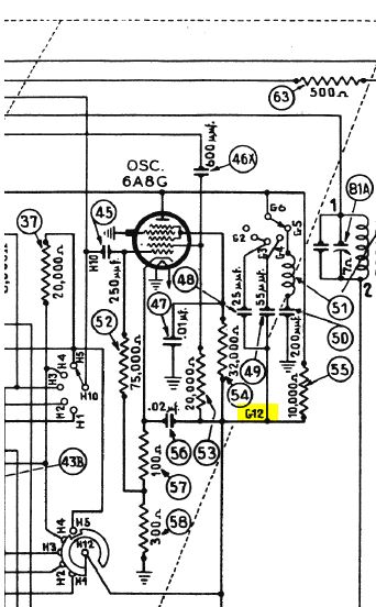
The 6A8's cathode should be about 400 ohms above chassis ground. Check your wiring around #'s 57, 58, and pin 8. May have a bit of extra solder or it may be bent over shorting it to the chassis.
This really make me appreciate my '36 116X, doesn't have all the bell and whistles of the 37-116 or the 38-116 but does sound good and is plenty loud! Have two of the 37-116 and after I get done with this 41-300 I might just dig into the manual tune set.
Happy Hunting!!!
When my pals were reading comic books
I was down in the basement in my dad's
workshop. Perusing his Sam's Photofoacts
Vol 1-50 admiring the old set and trying to
figure out what all those squiggly meant.
Circa 1966
Now I think I've got!
Terry
(This post was last modified: 08-07-2017, 11:18 AM by Radioroslyn.)
Posts: 76
Threads: 18
Joined: Nov 2015
City: Palmyra
State, Province, Country: Virginia
Thanks Terry! One quick question. The 38-116 code 121 parts listing shows that part 57 is a wirewound 10 ohm resistor. The schamtic shows part 57 as a 100 ohm resistor. I check the 1938 model changes and did not see this mentioned. Any idea which is correct?
Andy Sorrell
Palmyra, Virginia
Posts: 7,296
Threads: 268
Joined: Dec 2009
City: Roslyn Pa
Don't know, but do known the 0 ohms is less than both 10 or 100. What value is the circuit? That would be the number I'd replace it with if need be vs what the parts list or schematic sez. Don't think that is the problem. A little unusual that it's spec'd as a ww resistor. Be careful those low wattage guys look like a piece of string w/metal end and can be rather fragile, they don't like bending very much.
When my pals were reading comic books
I was down in the basement in my dad's
workshop. Perusing his Sam's Photofoacts
Vol 1-50 admiring the old set and trying to
figure out what all those squiggly meant.
Circa 1966
Now I think I've got!
Terry
Posts: 76
Threads: 18
Joined: Nov 2015
City: Palmyra
State, Province, Country: Virginia
Okay I have taken the RF chassis out again and am checking all my connections to the 6A8 and all the rest of the tubes and switch wafers in the RF subchassis. Good news is that I was able to find a 37-117 code 122 on craigslist and picked it up this weekend. I will VERY carefully take a look at that RF subchassis which is untouched and looking at the schematic nearly identical to my 38-116 code 121 (as least in the RF subchassis portion). I did find a little something that looked odd on ths schematic that I did not see addressed into 1938 model changes. On the schematic between part 146 switch wafer G it shows a connection from G6 to G12 - the schematic for the 37-116 code 122 shows the same connection going to H6 and that is how it is wired on the 37-116 and 38-116 i am working on. Is that am error on the schematic - should it be H6 or G12? Here is the portion of the schematic I am referencing (the G12 I am questioning is highlighted in yellow):

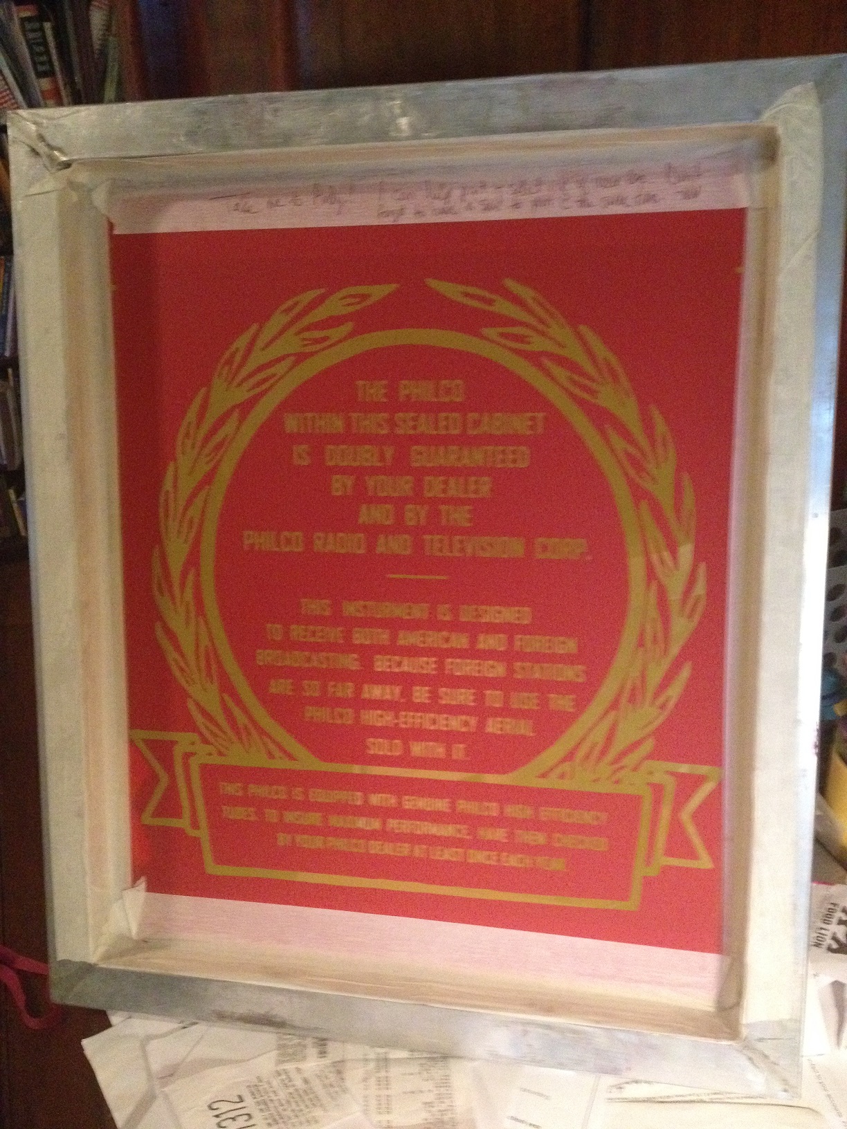
Also on another thread ( http://philcoradio.com/phorum/showthread.php?tid=16254) I mentioned where I was working on making a new back for this radio. I had a friend in the printing business make me a silk screen

of the Philco wording that was on the back from an logo I touched up. Now I just need to cut out the back from fiber board and silk screen it on - and I'll probably do some t-shirts while I am at it!
Andy Sorrell
Palmyra, Virginia
(This post was last modified: 08-22-2017, 12:41 PM by AVSorrell.)
Posts: 7,296
Threads: 268
Joined: Dec 2009
City: Roslyn Pa
I'm not sure. My best recollection is that the 37-116 sub chassis and the 38-116 are a bit different, the 38 I believe have some cost cutting features. Most are in the alignment area, less trimmers. This may explain some circuit differences. I've never had a 38-116 so I can't say it unequivocally it's from what I've read.
So to be rebuilding a 37-116 too? And might you be joining us up in Kutztown Pa in a few short weeks??
When my pals were reading comic books
I was down in the basement in my dad's
workshop. Perusing his Sam's Photofoacts
Vol 1-50 admiring the old set and trying to
figure out what all those squiggly meant.
Circa 1966
Now I think I've got!
Terry
Posts: 76
Threads: 18
Joined: Nov 2015
City: Palmyra
State, Province, Country: Virginia
Okay here is a video of the current status: [Video: https://youtu.be/CJlsGr9_7EM]
Getting a few stations but not clearly - would an alignment clear it up? All 5 bands seem to be working!
Andy Sorrell
Palmyra, Virginia
Posts: 7,296
Threads: 268
Joined: Dec 2009
City: Roslyn Pa
When you get it put back together things should improve a lot. Having long wires connecting the sub chassis to the chassis creates problems with capacitance and induction detuing the circuits they are attached to. Wouldn't bother to do any RF alignment until it's reassembled. Glad to hear you got all the bands work!
When my pals were reading comic books
I was down in the basement in my dad's
workshop. Perusing his Sam's Photofoacts
Vol 1-50 admiring the old set and trying to
figure out what all those squiggly meant.
Circa 1966
Now I think I've got!
Terry
(This post was last modified: 09-02-2017, 09:00 PM by Radioroslyn.)
Posts: 76
Threads: 18
Joined: Nov 2015
City: Palmyra
State, Province, Country: Virginia
Hey Folks -
So i got the radio subchassis put back together and have been testing the last month as I have had time. The volume is not strong - but I am picking up stations across all 5 bands. because the volume is weak, I have testing all the usual things- the 2 = 6L6G tubes are good and strong (nos from Bob Dobush) I have a replacement output transfromer - hammond 125 e using pins 4 and 6 for the secondary. I have a new rebuilt input transformer. I have check all the other tubes including the 6J5 driver and all check good - no shorts or any other issues. I also did an alignment of the broadcast band since i thought that could be impacting volume - but still not "booming" like it should be. I have checked the caps and resistors around the 6L6 tubes and driver tubes and they check good (particuarily resistors 134 and 135) I have noticed that the volume starts out louder and then once the tubes warm up its get lower. I am at a loss for what the issue could be at this point and it does not seem to be the obvious things. Really need some help on figuring out what the cause of the low volume is. -- Andy
Andy Sorrell
Palmyra, Virginia
Posts: 79
Threads: 8
Joined: Dec 2014
City: Wood River, Il.
It sounds like it is time to start checking tube voltages. Tube extenders really make things easier for this task, especially on the RF sub-chassis. At least that is where I would start. Good luck!
Chris H
N9WHH
Users browsing this thread: 1 Guest(s)
|
|
Recent Posts
|
|
Zenith H725
|
| Here's what the inside of AM IFT2 looked like, and the other pic shows the discs I made to take place of the mica and ke...EdHolland — 07:40 PM |
|
Zenith H725
|
| IF2 will need replacement caps. The arcing was severe enough that the mica is pitted and holed where the HT flashed over...EdHolland — 04:04 PM |
|
My Philco 37-116 Restore
|
| Measuring from center tap like the tube voltages show. Cap 127 is isolated from ground. Cap 127 shown in upper left of p...dconant — 08:05 AM |
|
My Philco 37-116 Restore
|
| Are you measuring relative to the centertap or the GND?morzh — 11:57 PM |
|
Philco 610B oscillator wiring
|
| Still not clear on the wiring interface between the 6A7 and oscillator. After refering to the available schematics and s...Tubester — 07:18 PM |
|
Refinishing Ideas
|
| My 37-116 code 121 is the best sounding radio i have...a daily driver. Since we are talking about "changes". ...poulsbobill — 07:18 PM |
|
My Philco 37-116 Restore
|
| Hello, I finally got brave enough to take the cans off the Expander Unit. Got the grid cap wires replaced and back toget...dconant — 06:50 PM |
|
Zenith H725
|
| I got into the first AM IF can today, and found its mica was cracked. Amazing that it was still working. This one makes ...EdHolland — 06:10 PM |
|
Philco model #20
|
| AHH HA , I got it and can’t thank you fellows enough , when I changed the capacitors I took the advice and did not unsol...onlyrick — 02:24 PM |
|
Zenith H725
|
| Hello Ed,
yes, I like letting projects run for few days to make sure they don't start acting up .
Sincerely Richardradiorich — 01:03 PM |
|
Who's Online
|
| There are currently no members online. |

|
 
|


![[-] [-]](https://philcoradio.com/phorum/images/bootbb/collapse.png)


