Posts: 7
Threads: 2
Joined: Jun 2020
City: kingston
State, Province, Country: Michigan
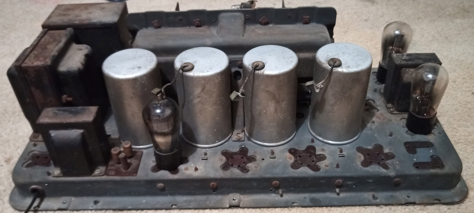
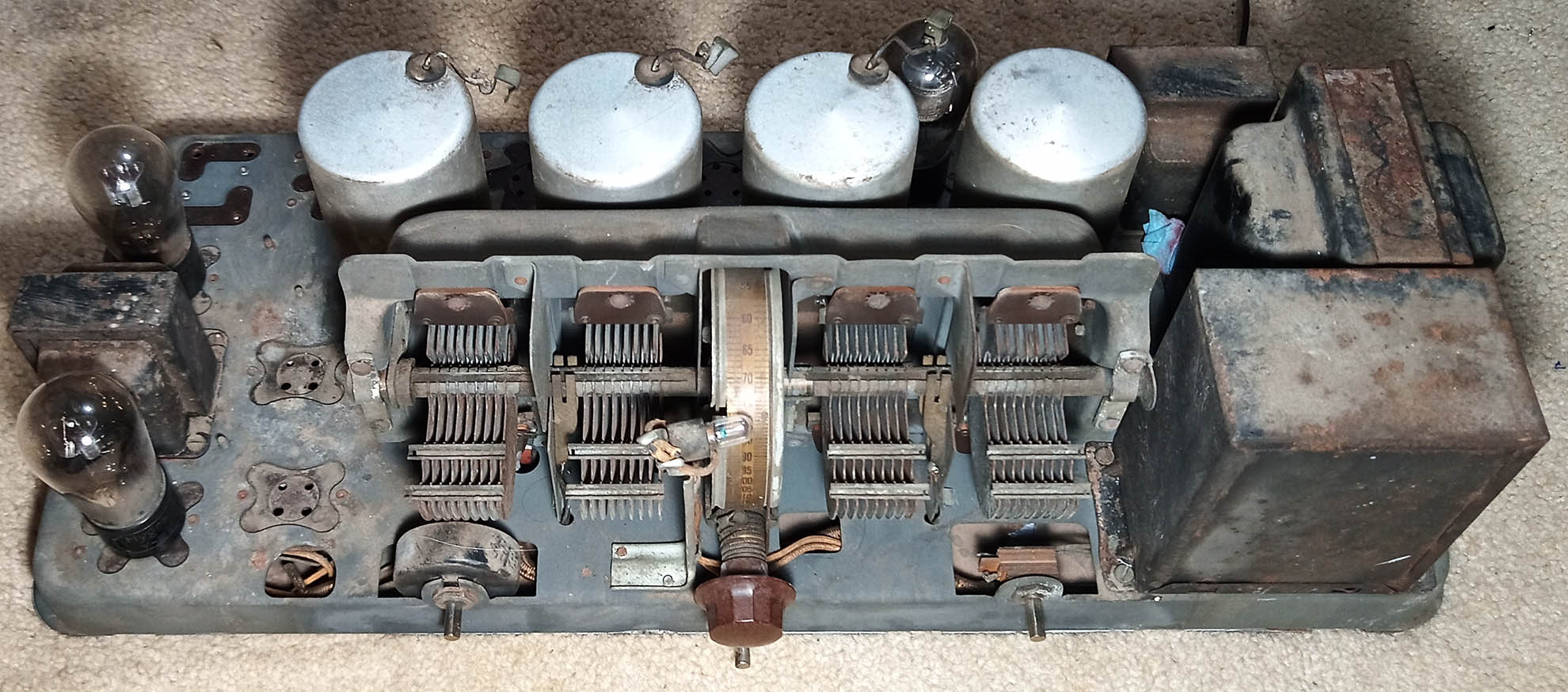
From what i gathered I got a Philco 65 low boy [Late] cabinet, but the chassis diagram dont match up according to the wiring diagram.
I bought the missing tubes based on what a 65 needed.. i have 2 unoccupied tube sockets. the tubes in the pics are a 224, 227, 227.
the 224 has the top hook up, and the 227's are either side of the transformer. that's what it came with. according to radiomuseum an 87 doesn't use 224 tubes. (
26 26 26 27 26 45 45 80)
I may have a swapped chassis and be on the wrong track for the tubes.

I'm use to working on modern technology. i'm having a hard time finding the information i need and getting it working.
The only story i have on it is it belongs to my stepdads dad or grampa. i'm trying to get it working as a fathers day gift.


Posts: 7,298
Threads: 268
Joined: Dec 2009
City: Roslyn Pa
Hi and welcome,
It's a 95 or 96 both are abt the same.
When my pals were reading comic books
I was down in the basement in my dad's
workshop. Perusing his Sam's Photofoacts
Vol 1-50 admiring the old set and trying to
figure out what all those squiggly meant.
Circa 1966
Now I think I've got!
Terry
Posts: 1,199
Threads: 49
Joined: Oct 2017
City: Allendale, MI
Posts: 7,298
Threads: 268
Joined: Dec 2009
City: Roslyn Pa
When my pals were reading comic books
I was down in the basement in my dad's
workshop. Perusing his Sam's Photofoacts
Vol 1-50 admiring the old set and trying to
figure out what all those squiggly meant.
Circa 1966
Now I think I've got!
Terry
Posts: 13,776
Threads: 580
Joined: Sep 2005
City: Ferdinand
State, Province, Country: Indiana
It's a model 95.
Notice the cylindrical capacitors, and the large format speaker socket - 1929 design. Philco switched to the bakelite block capacitors in mid-1930 when model 96 was introduced; the 96 also used a much smaller speaker socket.
--
Ron Ramirez
Ferdinand IN
Posts: 7
Threads: 2
Joined: Jun 2020
City: kingston
State, Province, Country: Michigan
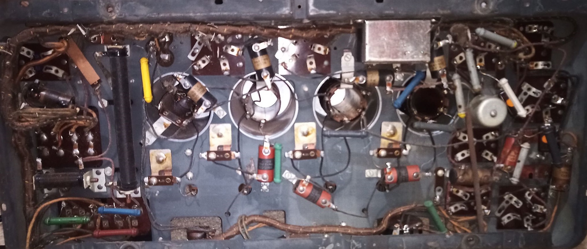
Thanks a lot guys, much appreciated. Sorry the middle picture was a little blurry.
I was starting to think it was a 96 after looking at more schematic photos. but then i seen a 96 chassis picture and it looked a little different.
I also forgot to make sure i was subscribed to my thread.. On most forum sites that's automatic. oops..
i got all the tubes for it. just need to replace the rest of the caps i wasn't sure about. The schematic link Radiorosyln posted helps a ton. thanks!
it helped me understand part 3787-A a lot better too. I didn't want to do anything with those until i was absolutely clear on it.
a reddit post i found talks about replacing carbon resistors. is that necessary? and all im seeing is wire wound resistors unless they look way different that what im thinking.
In the philco library im seeing a 95 early and 95 later schematic.
https://philcoradio.com/library/index.ph...chematics/
I downloaded both im not sure which i have. but there is little difference and I'll probably find out which when i have the time to do a thorough investigation of the wiring.
Posts: 7,298
Threads: 268
Joined: Dec 2009
City: Roslyn Pa
>replacing carbon resistors. is that necessary?
I just check to see if they are within tolerance (20%).
When my pals were reading comic books
I was down in the basement in my dad's
workshop. Perusing his Sam's Photofoacts
Vol 1-50 admiring the old set and trying to
figure out what all those squiggly meant.
Circa 1966
Now I think I've got!
Terry
Posts: 7
Threads: 2
Joined: Jun 2020
City: kingston
State, Province, Country: Michigan
okay, thanks for the help. I'll get into it this weekend.
i subscribed to receive an email notification of new replies but didn't receive any...
Posts: 325
Threads: 34
Joined: Dec 2019
City: Elkhart
State, Province, Country: Indiana
check your spam box, the email notifications from this site always end up in the spam box (that's the way it is with me anyways and I even tried adding the notifications email address to my safe sender list and it still ends up in the spam box, because apparently they use several different notification email addresses, from what I could see because no two notification email addresses are the same).


![[-] [-]](https://philcoradio.com/phorum/images/bootbb/collapse.png)


