Posts: 26
Threads: 7
Joined: Dec 2011
City: Eagle,
State, Province, Country: ID
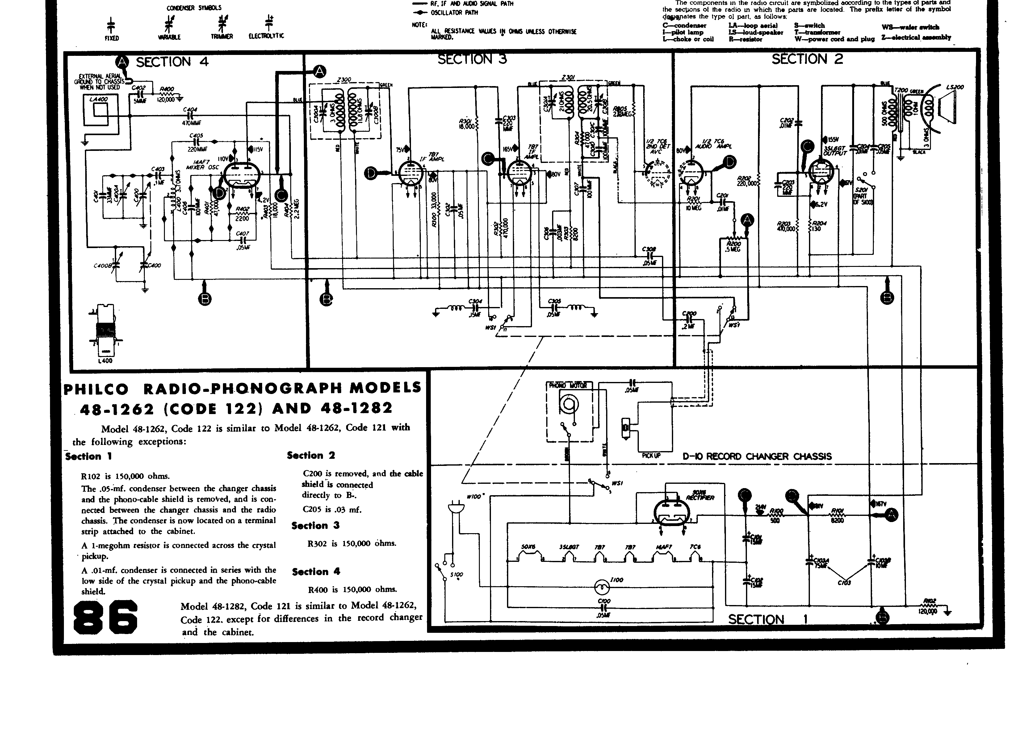
I am in the process of re-capping a Philco 48-1262 radio/phono combo. I noticed two capacitors, C304 and C305 both have wires wrapped around them. I would like to know the right way to replace these capacitors and still keep the coils working properly.
Any help would be helpful. Thanks
Posts: 26
Threads: 7
Joined: Dec 2011
City: Eagle,
State, Province, Country: ID
Here is a link to a photo of the caps and coils in question.
http://s1061.photobucket.com/albums/t480...thcoil.jpg
Posts: 13,776
Threads: 580
Joined: Sep 2005
City: Ferdinand
State, Province, Country: Indiana
See this page on Chuck's site for an explanation of these coil/cap combos.
http://www.philcorepairbench.com/tips/svctip37.htm
--
Ron Ramirez
Ferdinand IN
Posts: 4
Threads: 1
Joined: Sep 2020
City: Prattville
State, Province, Country: Alabama
Hi Friends. I have finally gotten around to asking where to start in the process of restoring my old 48-1262. I powered it up when I first started and found that some, but not all of the tubes lit up, so didn't leave it on long and started dissecting. Turning it over to reveal all of the caps, resistors, and wiring, I immediately noticed the problem cap, but I know I need to replaced them all. The one obvious bad one is a Philco 30-4518 that has burned open. It's .05 mF. So now that I know I have some rewiring to do, I was wondering if anyone has a general "shopping" list of all the caps, resistors, tubes, and other components that I will need to start the rebuild. I figure I'll get the radio itself working and then work on the finish of the cabinet.
Also, as you may know, mine has the built in record player. After reading a lot of posts about it, it being a 78rpm player, and the non-availability of the needle cartridge, I decided to improve upon it. I took an old Kenwood turntable that I purchased in the mid 80s and "fitted" it for the platform that goes into the Philco. It encompassed a lot of detail work, rigging, and removal of most of the original hardware, so I have lost the vintage look, but have a working turntable for my unit.
I did notice that the light bulb in my radio is not working. It looks like a standard 8W night light bulb. Is this correct?
Thanks for your help.
Posts: 1,084
Threads: 44
Joined: Feb 2015
City: Roseville, MN
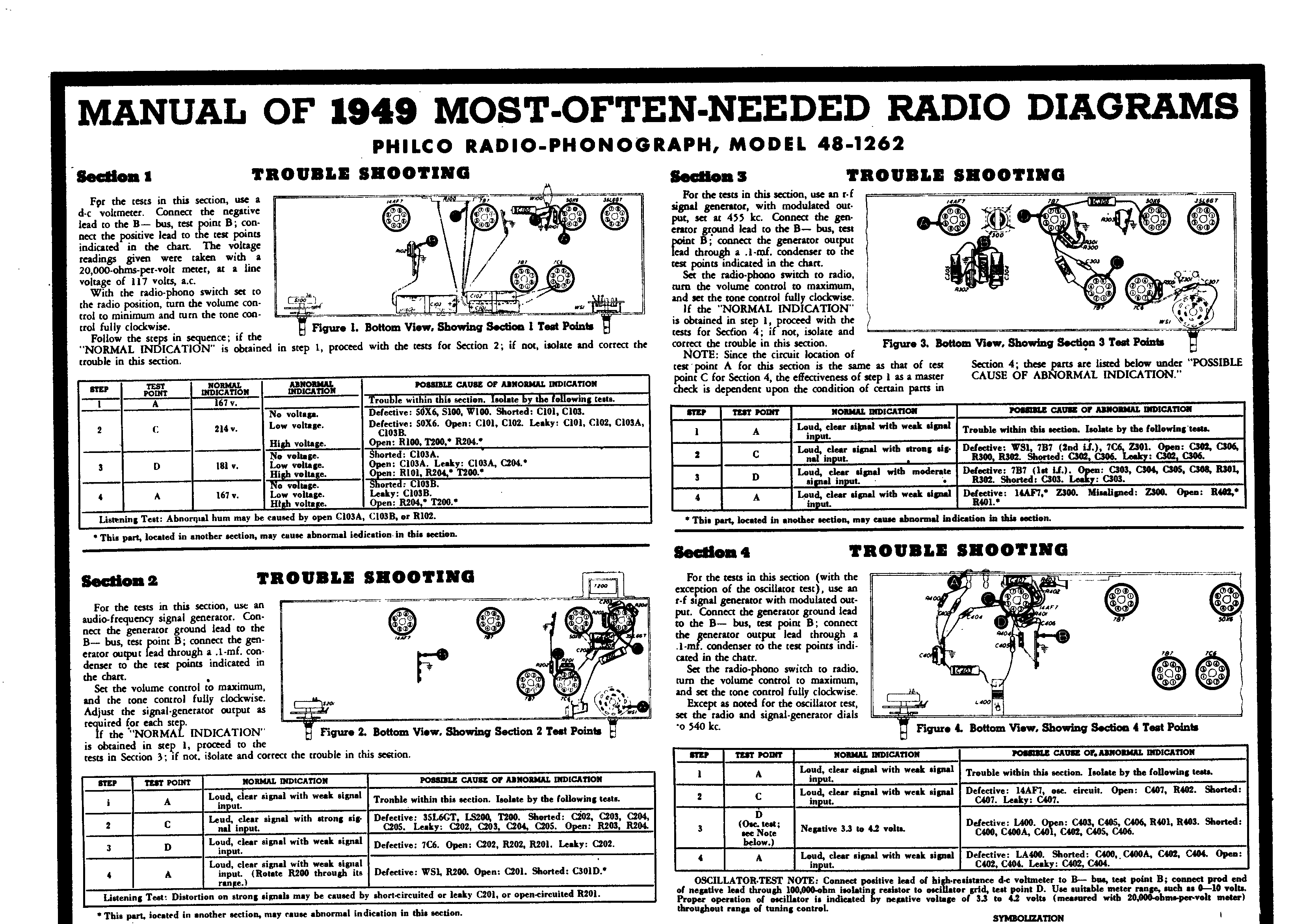
Hello Mike and welcome to the Phorum. First off the moderator today may move your post to a new thread, but don't get lost because we can start getting you moving on restoration. Yes, the light bulb is a 120 volt lamp, probably a C7 Christmas tree bulb. If you put another one in I would use a clear one. Get a schematic diagram from nostalgia.com. Next, do some component checking with a multimeter. Check all the transformers and coils for proper resistance and continuity. Keep us informed of your progress, you'll welcome the support and direction. Check resistors; I use 10%. Most will say 20% is good enough. Plan on replacing all the electrolytic and paper capacitors; they are well past their expiration. A lot of us order caps and resistors from Mouser Electronics. Use the schematic parts list for reference. Order capacitor values closest to the original value and it's ok to get 630 volt mylar film caps to replace the wax paper and 400 volt caps for the electrolytics. The 0.05mfd cap that fried is probably the line filter cap and should be replaced with a safety cap. Read up on the hot chassis issue and make sure you understand it. Don't power up the radio until the power supply filter caps have been replaced. Your new changer may have a magnetic cartridge which may not produce enough signal for the audio amplifier. You can check on that later.
Posts: 7,294
Threads: 268
Joined: Dec 2009
City: Roslyn Pa
Hi Mike,
Here's the service info:
https://philcoradio.com/library/download...8-1949.pdf
If you find finding anything via Mouser a daunting task you can give this site a try:
http://www.tuberadios.com/capacitors/ It doesn't the variety but for just rehabbing a radio it has a lot of the consumables.
GL
When my pals were reading comic books
I was down in the basement in my dad's
workshop. Perusing his Sam's Photofoacts
Vol 1-50 admiring the old set and trying to
figure out what all those squiggly meant.
Circa 1966
Now I think I've got!
Terry
Posts: 1,238
Threads: 30
Joined: Jan 2014
City: Wellborn Florida


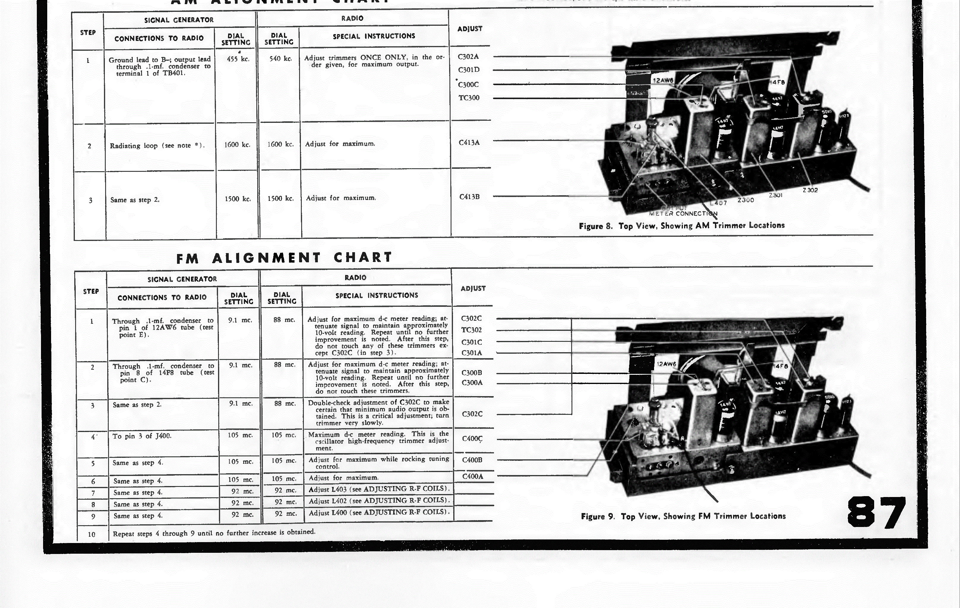
Some info from Beitmans.
Posts: 1,238
Threads: 30
Joined: Jan 2014
City: Wellborn Florida

Oops last page.


![[-] [-]](https://philcoradio.com/phorum/images/bootbb/collapse.png)


