Philco 46-480 Replacing Field Coil w/ Perm Mag (I know I know)
Posts: 1,216
Threads: 11
Joined: Jul 2020
City: Greenlawn
State, Province, Country: NY
Hi, RetroRev,
That all sounds about right. Next step is to inject an audio signal. Several places to do so, but the best point is the junction of C47, R26, C42 and R20. Of course, if the radio has a phono / FM Tuner / TV Input, that will work great! Make an adaptor cable where the "ring" and "tip" (The 2 contacts closest to the end of a 3.5 mm "TRS" (Tip, Ring Shield) headphone plug are each connected to a 10K resistor. The other ends of the resistors are joined together and toa 0.91 uF cap. That goes to the above junction. The shield (the long contact on the plug_ Connection is to chassis ground. Use a battery powered device such as a CD or MP3 player to inject a signal (maybe some Big Band music). If you get good audio, controllable by the radio's volume control, then the Amp is good. Let us know, then we can look at the next troubleshooting step.
"Do Justly, love Mercy and walk humbly with your God"- Micah 6:8
"Let us begin to do good"- St. Francis
Best Regards,
MrFixr55
Posts: 33
Threads: 2
Joined: Sep 2022
City: Ventura
State, Province, Country: CA
Ive got a rig I was using for another project made out of a bluetooth headset. Pretty much the same setup, + and - coming from the leads that were connected to the earbud.
That should work the same, right?
Posts: 33
Threads: 2
Joined: Sep 2022
City: Ventura
State, Province, Country: CA
Good news! Just piped some Stray Cats through it and it amplified just fine! Volume knob is crackly as H**l but nothing that can't be cleaned up a
Posts: 4,433
Threads: 419
Joined: Jun 2011
City: Boston
State, Province, Country: Massachusetts
Stray Cats Strut, tail in the air, oh yeah.
Paul
Tubetalk1
Posts: 1,216
Threads: 11
Joined: Jul 2020
City: Greenlawn
State, Province, Country: NY
Good Deal, RetroRev. You now know that your work with the speaker and resistor was good. Now, the bad news. Easier to troubleshoot the Audio section than the radio section, unless you have a signal generator. My $0.02 on what to do next:
If you have not done so, replace all of the paper caps. In addition, replace any mica caps around the detector area (for now, don't change any mica caps in the IF section.
Clean the heck out of the band switch and the tube sockets with Caig DeOxit or similar cleaner. While you're at it, clean the volume control. Loctal tube pins and socket connections can be funky. clean them too, r\\tighten contacts, and remove / replace the tues several times. Dunno why the issue exists with the Loctal tubes but not with the later 7 and 9 pin miniatures, compactrons, etc. Make voltage measurements on the IF and convertor tube, and ohm out the IF transformers RF and Oscillator coil. if voltage / resistance tests are good and band switch is good, go to next step.
Get a modern radio with a loop or ferrite loop antenna and tune it to a midband station on the broadcast band that you can pick up. This is your "Tester" Radio. Hold it near the convertor (1st Detector) stage. On the radio you are servicing, tune throughout the broadcast band. If the tester radio squeals, or goes quiet, then the convertor stage is working, at least the oscillator section is working.
Touch the stator of the tuning cap section associated with the RF in section of the convertor (C16? Schematic says wire is white with red tracer) with a long wire. If stations are picked up, check the RF coils or the band switch.
Good luck.
"Do Justly, love Mercy and walk humbly with your God"- Micah 6:8
"Let us begin to do good"- St. Francis
Best Regards,
MrFixr55
Posts: 13,776
Threads: 580
Joined: Sep 2005
City: Ferdinand
State, Province, Country: Indiana
Warning: Don't use DeoxIT on volume or tone controls. Use Caig FaderLube instead. DeoxIT can damage the old, thin, fragile carbon strips of potentiometers (i.e. volume and tone controls).
Loctal tube socket contacts can be cleaned with one of those tiny brushes designed for use between one's teeth, sprayed liberally with DeoxIT (don't use that brush on your teeth afterwards  ). DeoxIT can also be used on switches without worry.
--
Ron Ramirez
Ferdinand IN
Posts: 1,840
Threads: 117
Joined: May 2008
City: Omak
State, Province, Country: WA
Hello Ron,
Yes I just watched a video on the subject showing how it damages controls one of my go to is Nu-trol Control Cleaner !
RetroRev, that is great news and the volume control is a minor issue .
Sincerely Richard
Posts: 1,216
Threads: 11
Joined: Jul 2020
City: Greenlawn
State, Province, Country: NY
Hi Gang,
Thanks for that info, I stand corrected. No DeOxIt on Potentiometers!!
"Do Justly, love Mercy and walk humbly with your God"- Micah 6:8
"Let us begin to do good"- St. Francis
Best Regards,
MrFixr55
Posts: 1,824
Threads: 114
Joined: Jul 2014
City: Sneedville, TN
Ah ! For the days of carbon tetrachloride ! Too bad the tree huggers outlawed it. It was what we used to use to clean pots back in the day. I had a bottle of it for years, but it finally ran out.
Posts: 33
Threads: 2
Joined: Sep 2022
City: Ventura
State, Province, Country: CA
Right, well about the caps...


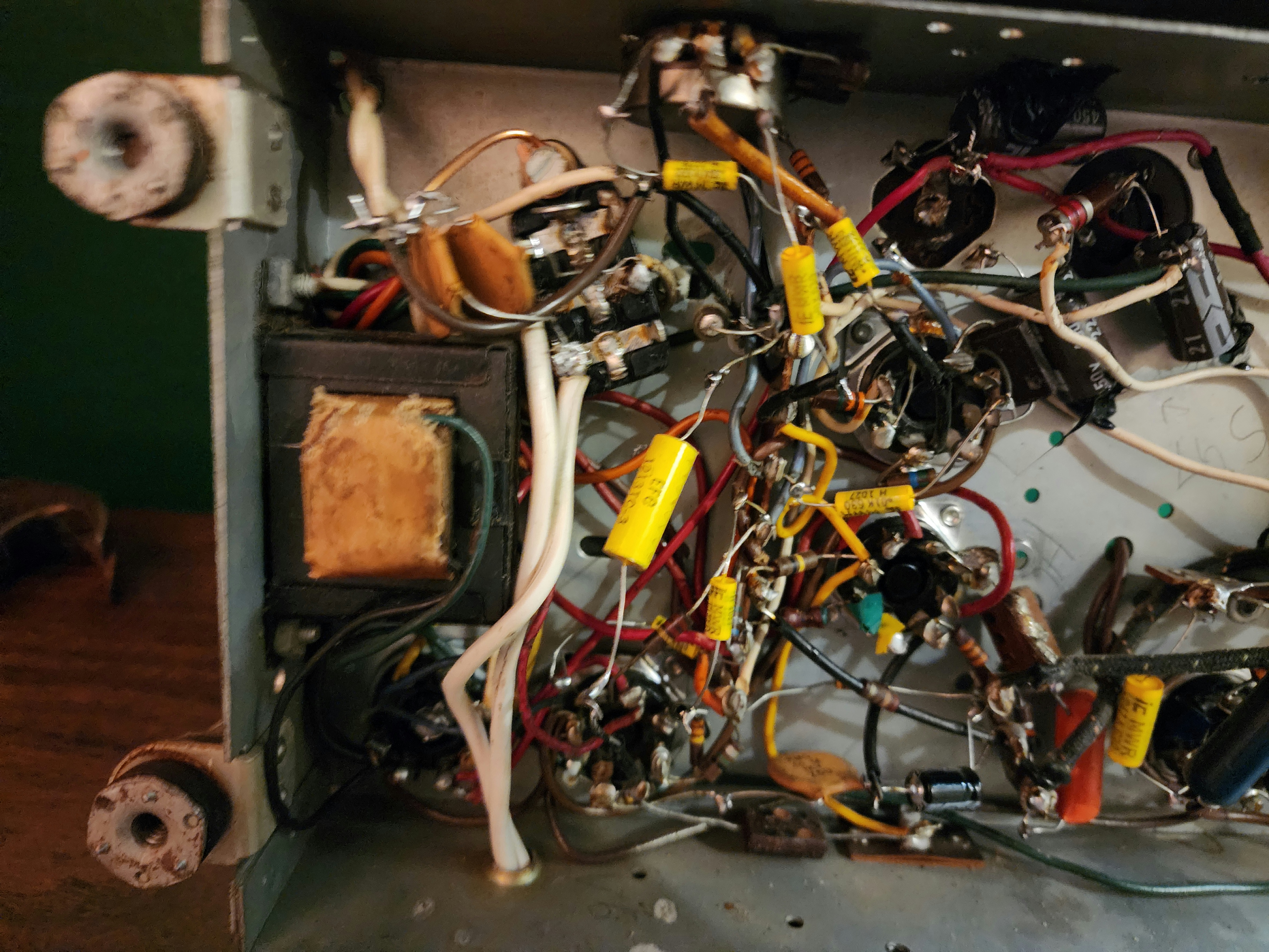
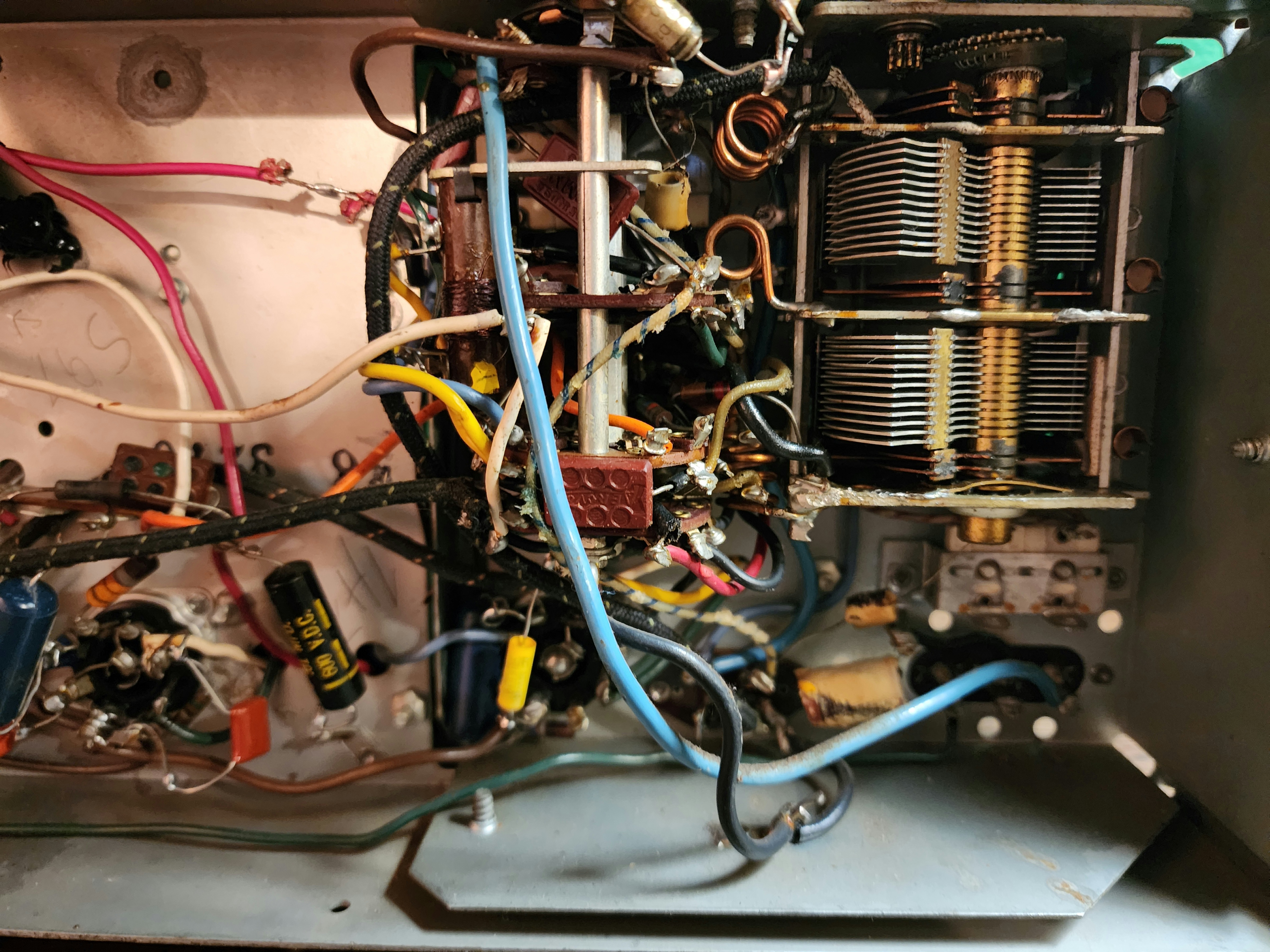
As you can see, whomever owned this thing before did some extensive work on it and although I know what you're going to say next, I'm dreading having to go through each and every one to double check their work...
As for cleaning, I've been using 99% IPA for most of the cleaning. I really don't like using aerosols, as it seems no matter how careful I try and be, I always end up spattering on something that shouldn't be spattered on and leaving a discolored mark somewhere.. that being said I do believe I have a can of Nu-trol somewhere in the "fire make go boom" cabinet at the shop if IPA is out of the question.
Posts: 33
Threads: 2
Joined: Sep 2022
City: Ventura
State, Province, Country: CA
Also, I feel it's worth noting that I get no static at all on any bands
Posts: 1,840
Threads: 117
Joined: May 2008
City: Omak
State, Province, Country: WA
Hello RetroRev,
Yes projects like this can take the most time because you have to check everything to make sure it is right !
Sincerely Richard
Posts: 33
Threads: 2
Joined: Sep 2022
City: Ventura
State, Province, Country: CA
The part I'm most salty about, is I'm not sure he even used the same color coding when he rewired it..
Posts: 1,216
Threads: 11
Joined: Jul 2020
City: Greenlawn
State, Province, Country: NY
There does seem to be a lot of good work there. I especially like the fact that the filter caps are RTVed to the chassis. One thing to try is to verify that B+ on plates and screens of the IF tubes and plate voltages on the Osc and Mixer are somewhere where they belong. Please be careful of high voltage when doing this and the following steps! Try to touch the grid of each IF tube (through a capacitor to prevent or limit shock) to inject some hum. If you hear hum, static or clicks, that means that something is getting through the IF (yeah, an IF shouldn't pass 60Hz Hum but in a noisy environment with Romex cable, fluorescent lights, computers, etc... If nothing, ohm the IF transformers and replace the 6H6. It appears that it is both the FM Discriminator and AM Detector. There may also be an issue with the band switch. Unfortunately for the issue that you are having, a signal generator would be of great help. The IF on this set is 455Hz. If you have another radio with this IF Frequency, you can Frankenstein a signal generator or signal injector from it. Of course, if the Signal Injector set is an AC / DC AA5, then us an isolation Xformer.
The 2nd IF Output Xformer is rather interesting. It has to be because it is for both AM and FM. There are some capacitors in that can. Dunno if these get the dreaded SMD but when all else is exhausted.
Hope all of this helps.
"Do Justly, love Mercy and walk humbly with your God"- Micah 6:8
"Let us begin to do good"- St. Francis
Best Regards,
MrFixr55
Posts: 33
Threads: 2
Joined: Sep 2022
City: Ventura
State, Province, Country: CA
Oh yeah! I know first hand how spicy this thing can be! Nearly gave myself a perm the other day checking voltages xD Ain't the first and, unfortunately, probably won't be the last. I would swear I was a lightning rod in a past life ?
As for the rest of it, hmm.. Well about 80% made its way through. Nothing that a little Googling of the jargon won't clear up though.
I -do- have a signal generator.. Kind of.. It's on time out at the shop currently for letting its magic smoke out a little after a co-worker "fixed" something on it. Still not sure what exactly to be honest. I'll pull it out tomorrow and see if it's a quick fix or a doorstop.
-Rev
Users browsing this thread: 3 Guest(s)
|
|
Recent Posts
|
|
The list of my radio & TV collection!
|
| A little bit of positivity in our feed...
My new video...
Test - the Philco 16B vs Philco 37-116 de Luxe / Test - the ...RadioSvit — 12:14 PM |
|
Refinishing Ideas
|
| Thanks. I will look into.
Billpoulsbobill — 11:23 AM |
|
My Philco 37-116 Restore
|
| Why do the flood lights have 2 wires running to the shell of each light when the inner conductor only has one to each?
...dconant — 10:54 AM |
|
Philco 46-480 Electronic Restoration
|
| OOPS!!
if there is a "flag" running up the side of the tube that touches the shield, then yes, a shield belon...MrFixr55 — 10:03 AM |
|
Philco 46-480 Electronic Restoration
|
| Thanks for pointing out that shield! I will try to find out where else it may belong. I simply installed it back where i...jrblasde — 10:02 AM |
|
Philco 46-480 Electronic Restoration
|
| Very nice job. A real contrast between how easy the main chassis is to work on, vs how tightly the RF chassis is packed...MrFixr55 — 09:31 AM |
|
Philco 46-480 Electronic Restoration
|
| After sleeping on it, I believe the issue is that I may have forgotten to install a ground connection between the RF cha...jrblasde — 09:21 AM |
|
Refinishing Ideas
|
| Hi Poulsbobl,
I think that you could get away with it. In the Philco Library, there is a parts listand specs for sp...MrFixr55 — 11:54 PM |
|
Philco 46-480 Electronic Restoration
|
| The sleeving for the transformer arrived early, so I went ahead and finished reassembling. The chassis looks far better ...jrblasde — 10:15 PM |
|
Philco 610B oscillator wiring
|
| I don't know what you are referring to when you say "tube cathode ground". Ground is a connection to the chass...RodB — 05:56 PM |
|
Who's Online
|
| There are currently no members online. |

|
 
|


![[-] [-]](https://philcoradio.com/phorum/images/bootbb/collapse.png)


