Posts: 3
Threads: 1
Joined: Nov 2023
City: Hamilton
State, Province, Country: Ontario, Canada
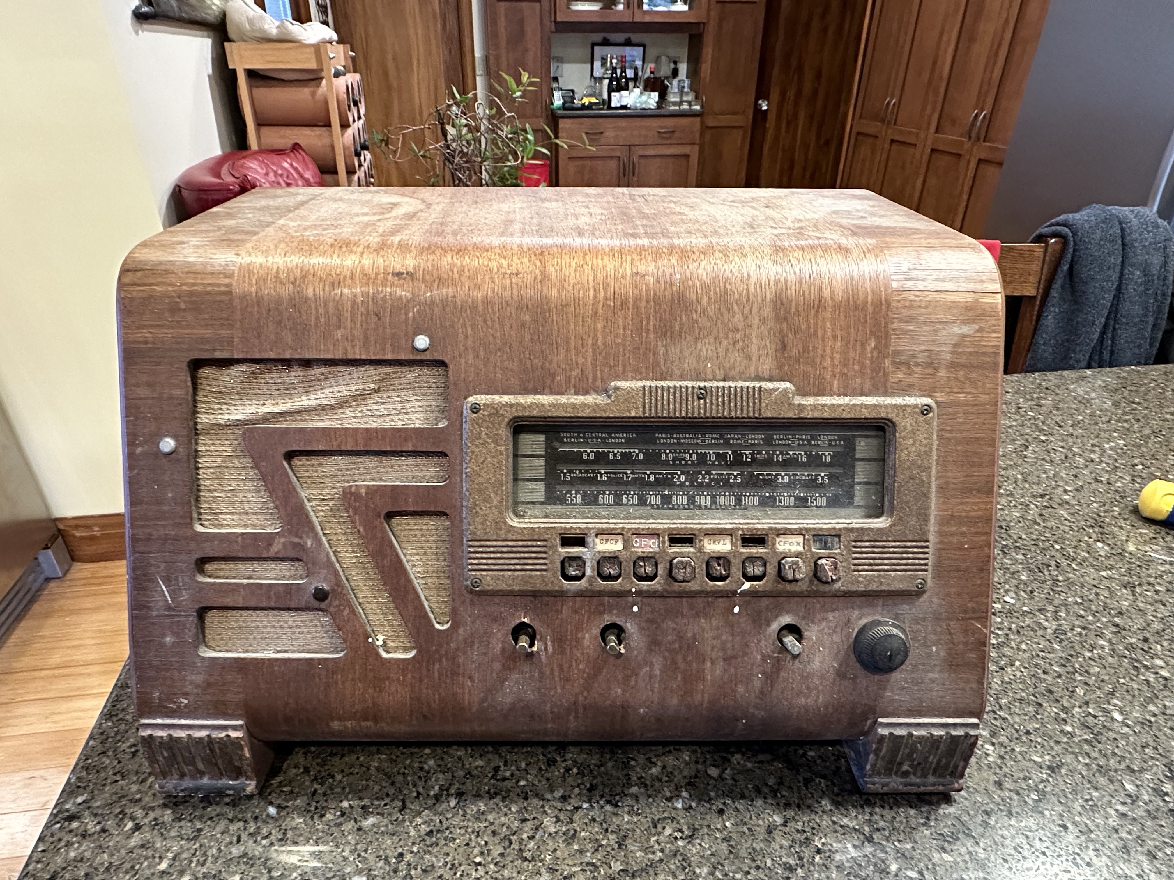
I recently rescued up a Philco push button radio from the local dump.
All of the exterior paper labels on the back are missing. It looks like a 39-25T, but has eight tubes.
On the inside of the case there is a tube diagram that says 39-6443E, but I can find no reference to this model on the internet.
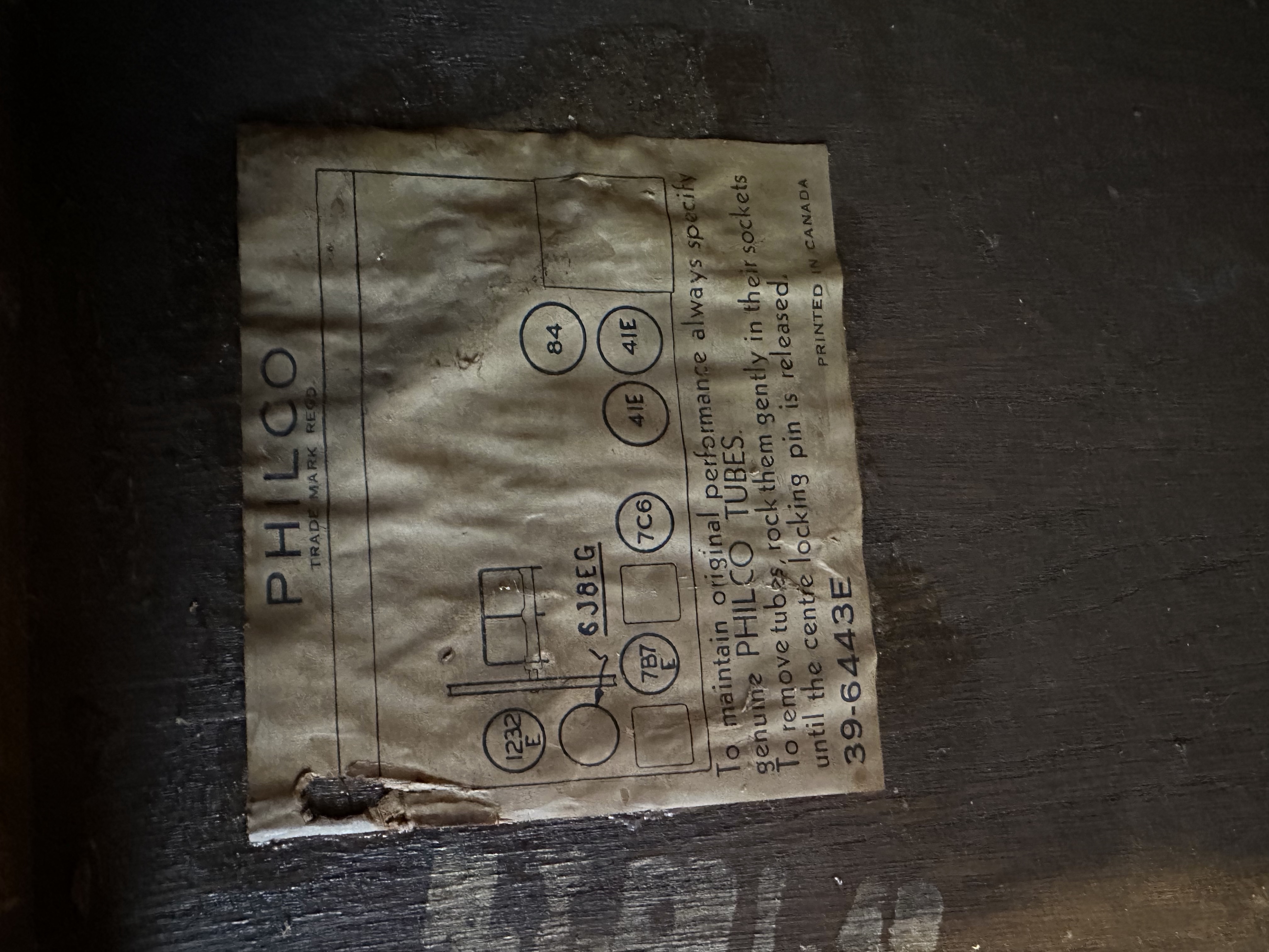
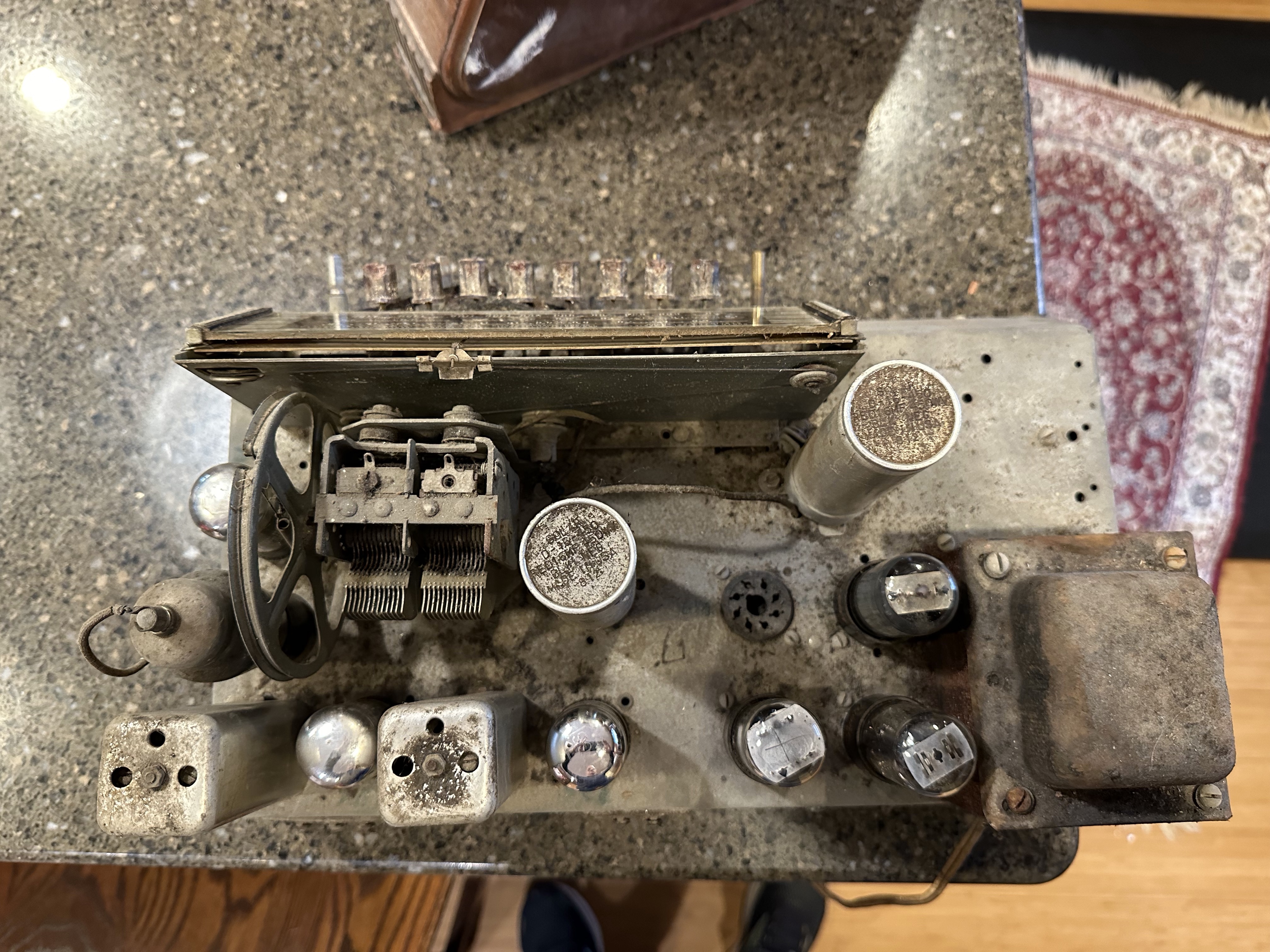
The tube diagram shows seven tubes, but the chassis actually has EIGHT sockets, one of which is empty. The empty socket has 6V6 written in pen beside it.
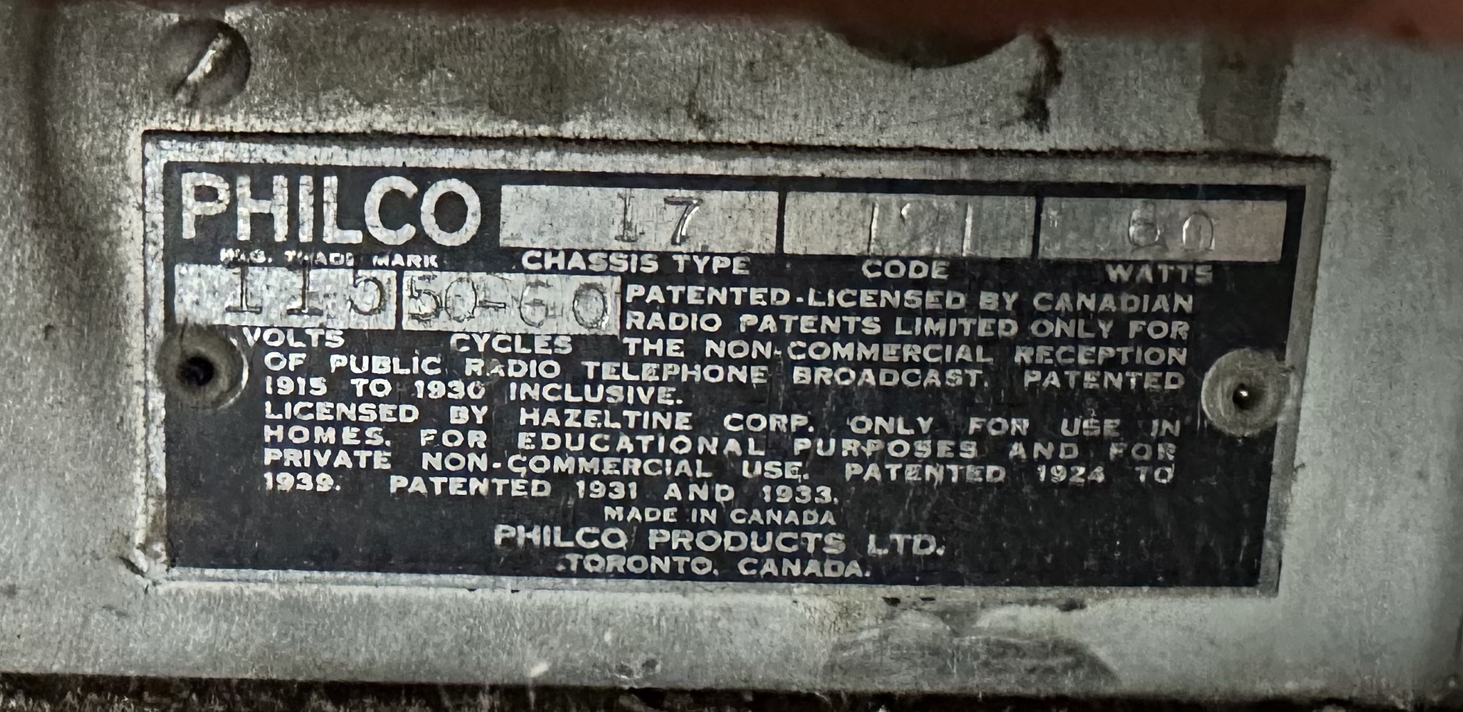
The radio was produced in Canada, based on the tag on the back of the chassis
I would like to get schematics and attempt a restoration, but don’t know where to go from here, as I don’t trust the model number specified, since the tube count is wrong. In addition, the rectifier tube on the tube diagram is in a different location on the chassis, so the diagram is obviously wrong.
I wondered if the radio had been modified to add the additional socket, but it looks original.
Any help or advice on how to proceed would be greatly appreciated.
Posts: 68
Threads: 7
Joined: Oct 2017
City: bloomfield, ct
Just an observation. The Canadian model 17AT was equivalent to the US produced 40-155 which used 7 tubes. The 4 tube sockets adjacent to the transformer look to be attached to the chassis with screws (and probably nuts underneath). I believe that the factory tube sockets were riveted to the chassis. I suspect that there have been changes but very old ones.
Posts: 889
Threads: 51
Joined: Feb 2013
City: Shenandoah,
State, Province, Country: Pennsylvania
That number 39-6443E is probably the part# for the label itself!
Ron
Bendix 0626. RCA T64 Philco 20B
Philco 41-250. Philco49-500
GE 201. Philco 39-25
Motorola 61X13. Philco 46-42 Crosley 52TQ
Philco 37-116. Philco 70
AK 35 Philco 46-350
Philco 620B. Zenith Transoceanic B-600
Philco 60B. Majestic 50
Philco 52-944. AK 84
Posts: 3
Threads: 1
Joined: Nov 2023
City: Hamilton
State, Province, Country: Ontario, Canada
Thanks guys!
@patrician56 - I’m also wondering about the possibility of the addition of a push-pull output stage.
@462ron - I too was thinking about the number on the tube diagram being a part number. Does anyone else have a similar radio with a tube diagram that would confirm this theory?
Finally, if the radio has been modified, the big question is deciding what to do moving forward:
1 - Attempt to get it working in its current state (without a schematic)
2 - Revert to the original design (assuming I can get a proper schematic)
3 - Leave it non-functional but clean up the cabinet
Paul
Posts: 125
Threads: 17
Joined: Jan 2018
City: Kingsville Ohio
From the top, your chassis looks exactly like an American Philco 40-180 chassis. If you get the schematic for the 40-180 and run out the circuits, it may be the same. Just my observation.
Dick
(This post was last modified: 11-24-2023, 11:02 PM by madsowry.)
Posts: 330
Threads: 30
Joined: Aug 2017
City: Hay Lakes, Alberta,Canada
Reproduction push buttons are available from Renovated Radios, as are the rubber chassis mounts.
Posts: 68
Threads: 7
Joined: Oct 2017
City: bloomfield, ct
I think that you will find that your radio already has a push - pull output stage - the 2 - #41 tubes.
Philco offered a number of radios in the 1939 - 1942 era in both table and console versions that offered this "slant dial" chassis with a few variations. Your model uses the same cabinet as a US 40 - 155T, however that radio used an 8-tube layout while your radio appears to have been originally a 7-tube layout. The US model 40 - 150T used a 7-tube layout. The 1 additional tube for the 40 - 155 is listed as a "diode detector".
In any event, these radios perform very nicely and sound great. I had the 1941 model 41 - 255 which has a 9-tube layout, some of which are the "loctal" tubes that Philco was pushing that year. I did it for a friend and he has gotten a great deal of enjoyment out of it.
Check out the service information on the Philco library section of the Phorum site and compare the schematic for the 40 - 150, 40 - 155 and the 40 -180 variations with what you have.
Posts: 467
Threads: 31
Joined: Sep 2009
City: Lapeer
State, Province, Country: MI
My 2 cents. This is a Philco 40-155 based on the cabinet design over the speaker. It has been modified, evidenced in part because of the transformer. It isn’t squarely on the chassis (hanging over the edge) and appears to be a replacement. As 6V6’s aren’t part of the original tube line-up, someone wired in some octal sockets to sub for the 41’s and the 84. In fact, there were NO octal tubes in the tube line-up. Checking the components underneath and tracing the circuit would be the first step.
Joe
Matthew 16:26 "For what does it profit a man if he gain the whole world, yet lose his own soul?"
(This post was last modified: 11-30-2023, 02:16 PM by Joe Rossi.)
Posts: 3
Threads: 1
Joined: Nov 2023
City: Hamilton
State, Province, Country: Ontario, Canada
Yes, I think that’s what happened. I’m away from home for a week but on my return I will Start to create a schematic from the components in their current state. It also appears that a newer speaker has been wired to the output withoue]t a proper transformer between the two, and I’m guessing this is going to be an issue. I’ll know more once I’ve mapped it out. Hoping I can still read the test on the axial capacitors…
Posts: 4,928
Threads: 54
Joined: Sep 2008
City: Sandwick, BC, CA
Actually the 6J8EG is an octal based tube, but the #41s and the #84 were six pins, the 7B7 and 7C6 were loctals. I'm guess that the eighth tube was from someone adding a phase invertor as opposed to the screen grid inversion setup the radio had according to the tube chart. Incidentally I think the rectifier tube was put in the wrong socket, although it was rewired to accept a 5Y3/5Y4 but there would be no reason to relocate it, power transformer may also be a replacement. Schematics for Canadian Philco sets were published in the RCC manuals, and whilst many were copies of U.S sets many had changes made like different tube types substituted, and more cloth wire and less gutta percha/rubber wire used.
Regards
Arran
Posts: 7,305
Threads: 270
Joined: Dec 2009
City: Roslyn Pa
The 84/6Z4 is a 5 pin job. Do note that the 5Y3 and 5Y4 are not interchangeable because the filament and plate pin are wired differently. Philco sets that have the original socket for the rectifier some of the reciprocals for the pins are deleted. This means if you happen to have a 5Y3 and not a 5Y4 you can't add a few jumpers so both tubes could be used. Those sneak! This doesn't apply to this set as the socket is a replacement.
When my pals were reading comic books
I was down in the basement in my dad's
workshop. Perusing his Sam's Photofoacts
Vol 1-50 admiring the old set and trying to
figure out what all those squiggly meant.
Circa 1966
Now I think I've got!
Terry
(This post was last modified: 11-30-2023, 09:51 AM by Radioroslyn.)
Posts: 467
Threads: 31
Joined: Sep 2009
City: Lapeer
State, Province, Country: MI
Arran, You are correct about the 6J8. However, the 40-155 has 8 tubes; a 1232, a 7C6, a 7A6, a 7J7, a 7B7, an 84, and two 41’s. What I can’t see is why the label only shows 7 tubes. Maybe a 40-150 chassis modified? It’d be nice to know what the replacement tubes are.
Joe
Matthew 16:26 "For what does it profit a man if he gain the whole world, yet lose his own soul?"
Posts: 7,305
Threads: 270
Joined: Dec 2009
City: Roslyn Pa
Looks like someone slipped a 6SN7 in there next to the 5Y3.
When my pals were reading comic books
I was down in the basement in my dad's
workshop. Perusing his Sam's Photofoacts
Vol 1-50 admiring the old set and trying to
figure out what all those squiggly meant.
Circa 1966
Now I think I've got!
Terry
Posts: 1,267
Threads: 32
Joined: Jan 2014
City: Wellborn Florida
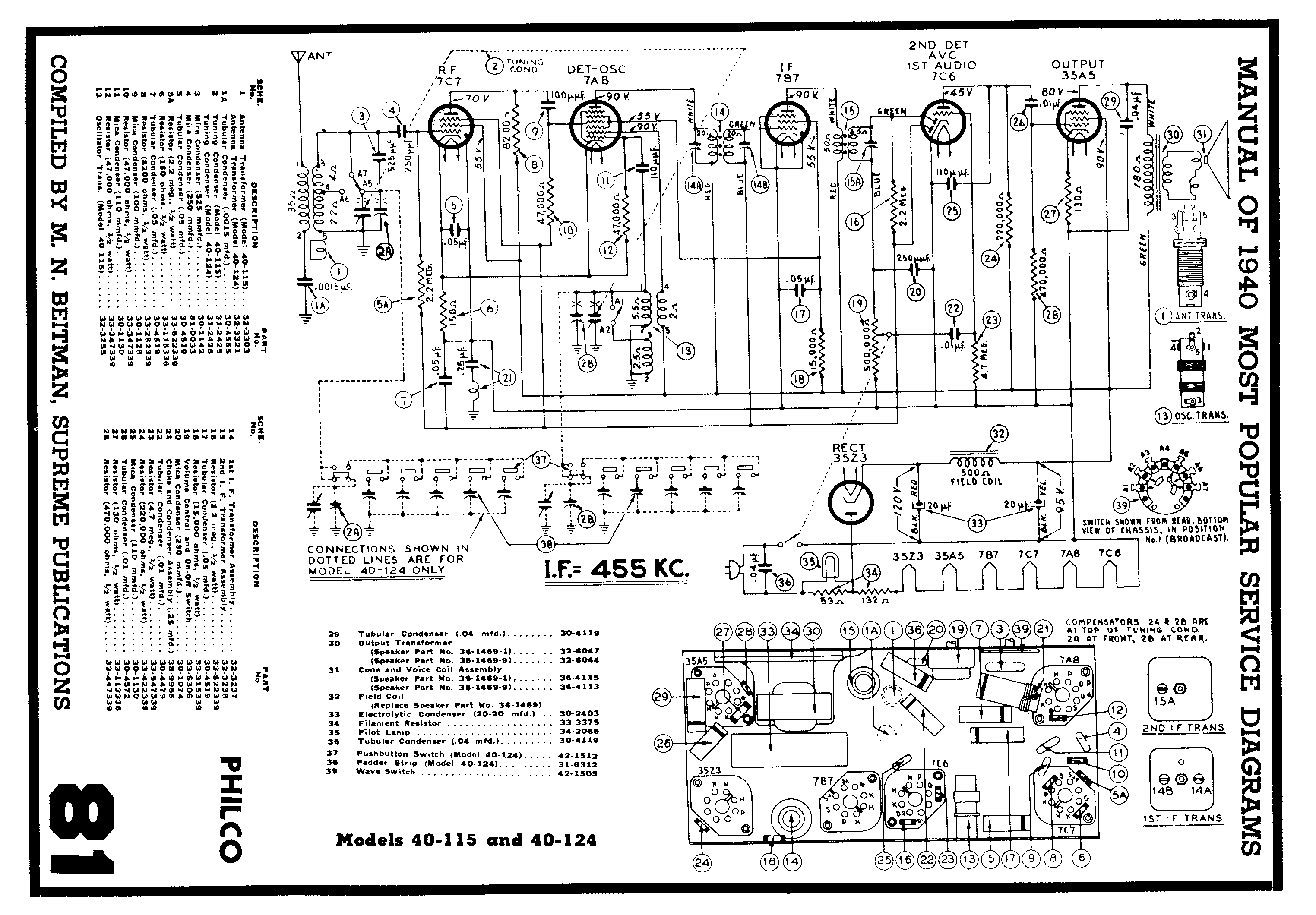
Beitmans Philco 40-155
Posts: 467
Threads: 31
Joined: Sep 2009
City: Lapeer
State, Province, Country: MI
David, This schematic is for the 40-115. 40-155 is on page 85 of the 1940 Beitman. The Riders is in vol.10.
Joe
Matthew 16:26 "For what does it profit a man if he gain the whole world, yet lose his own soul?"
(This post was last modified: 11-30-2023, 09:56 PM by Joe Rossi.)
Users browsing this thread: 1 Guest(s)
|
|
Recent Posts
|
|
Rogers Majestic R-646
|
| By the way, the bypass you suggested is a rare solution in some circuits.
For example, this schematics solution is used...Vlad95 — 01:43 PM |
|
Rogers Majestic R-646
|
| No, you are wrong, because you did not know the details.
Unfortunately, only ONE winding out of six is intact in both t...Vlad95 — 01:14 PM |
|
Rogers Majestic R-646
|
| The output 45s are still in push-pull because the transformer secondary winding is still in the grid circuit providing o...RodB — 11:52 AM |
|
Rogers Majestic R-646
|
| Thanks RodB for the help.
But this is not a real solution to this situation, not even a temporary one. Because the firs...Vlad95 — 11:34 AM |
|
Philco Model 16 wiring question
|
|
I was going to check the voltages as you suggested and hooked it up to my dim bulb. It appears I have a short. The bul...bobclausen — 10:34 AM |
|
Rogers Majestic R-646
|
| You can bypass the interstage transformer by disconnecting the primary, connect a load resistor of about 10k - 20k to th...RodB — 09:40 AM |
|
HiFi (Chifi) tube amp build - but my own design.
|
| So, here's Prince on stage halfway through Purple Rain when he stoops down to his tech and says "Rod, pull out that...RodB — 09:17 AM |
|
Rogers Majestic R-646
|
| Today I finished inspecting all the parts. The result is not very pleasing.
The first positive news:
1) The power tr...Vlad95 — 11:40 PM |
|
HiFi (Chifi) tube amp build - but my own design.
|
| Well, found muh culprit. After using socket test adapters and finding voltages all ok, swapping 6V6s, no avail, swapped ...TV MAN — 11:18 PM |
|
HiFi (Chifi) tube amp build - but my own design.
|
| Well, maybe - maybe not :lol: It's been an interesting project so far! Something so simple, yet so cranky. The 1st one ...TV MAN — 05:12 PM |
|
Who's Online
|
| There are currently no members online. |

|
 
|


![[-] [-]](https://philcoradio.com/phorum/images/bootbb/collapse.png)


