Philco 42-345 Restoration/Repair
Posts: 63
Threads: 2
Joined: Mar 2025
City: Bristol
State, Province, Country: VA
We'll guys I am at a standstill trying not to pull the band selector switch out. In the meantime, I am wondering about the tubes. I haven't done anything with the tubes and currently don't have a tube tester, and it appears my multi-meter doesn't check continuity. I am attaching a picture of the tubes and wonder if there is any way to distinguish them apart? Most of them I can't tell what number they are and one that stands out is 7C5 that based on the schematic should be 7B5. One of the XXL looks to be 7?7. I found a GE tube substitution chart that says a 7A4 can replace an XXL but "(May require components or adjustments besides those of Nos 1,2 or 3). The other adjustments include wiring change, socket change and shielding.
The GE chart shows a possible replacement for the 7B5 is 6K6GT/G with a socket change. 7C5 doesn't show as a sub for the 7B5.
So now I am wondering if when it was worked on prior if they were changed from original. All except the 7Y4(Delta) says Philco.
My main question is there a way to tell them apart? I am on the search for a reasonable tube tester
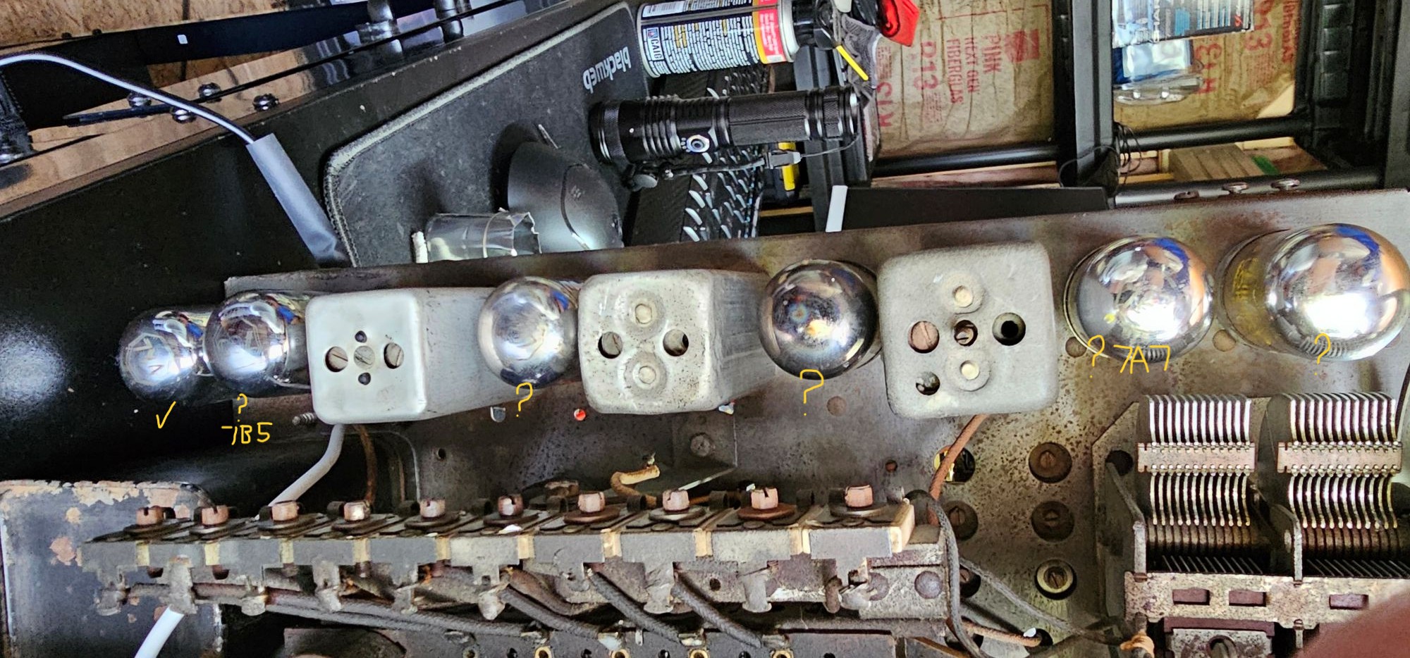
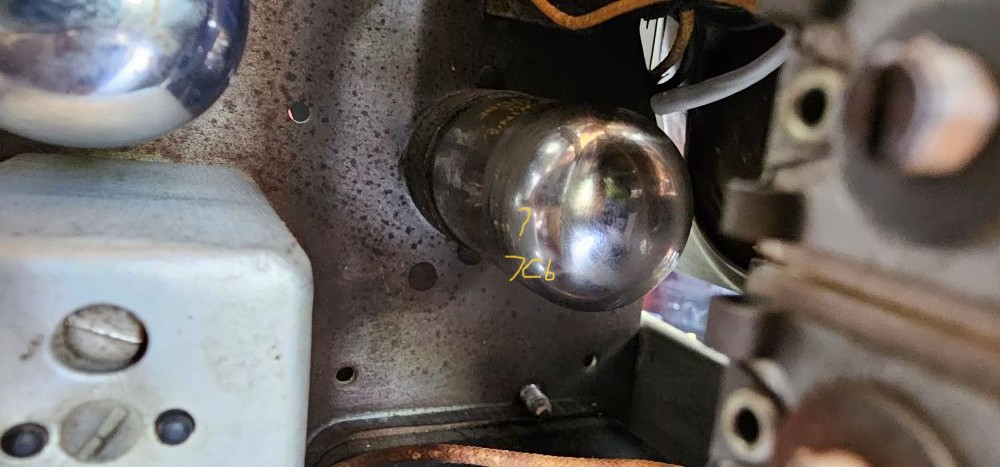
All the radio does now is a constant buzz/hum. Which it did the last time I changed the band selector while playing.
(This post was last modified: 06-20-2025, 01:51 PM by osanders0311.)
Posts: 1,797
Threads: 55
Joined: Feb 2015
City: Roseville, MN
The tubes are all loctal, there's no need to change that. The trouble with local tubes is corrosion on the pins and they cannot be cleaned up with water without wiping off the label. Missing labels might show up if the glass is set in a freezer for about 4 minutes, then removed. Look carefully at an angle, usually on the top, where the tube number goes and you might see the number faintly. If you do get the number have a sharpie ready to mark the base. You may have to buy tubes to replace the unknown ones. Check with Bob Dobush at findatube.com. The symptoms you're getting may be from bad contact on the tube pins; clean the sockets with Deoxit and a brass brush on the pins.
Posts: 63
Threads: 2
Joined: Mar 2025
City: Bristol
State, Province, Country: VA
Thank you, Rod, for the information of findatube.com, I am taking a chance and ordering the tubes they were very reasonable. The freezer method didn't work and since a couple appeared to not match the schematic, I'll take the chance and replace them.
Posts: 1,797
Threads: 55
Joined: Feb 2015
City: Roseville, MN
Just remember to not use water or water-based cleaner to clean loctal tubes and Philco phenolic dials.
Posts: 2,327
Threads: 23
Joined: Jul 2020
City: Greenlawn
State, Province, Country: NY
A 7C5 would work in place of a 7B5 but not exactly well. The pin diagram is the same, but the grid bias voltage and output transformer impedance would be different. the filament current of the 6C5 is only slightly higher There will be sound but possibly distorted. The 7B5 is the equivalent of a 6K6. The 7C5 is the equivalent of 6V6. You could likely use the 6C5 for now for testing purposes.
I cannot find statistics for the 6B5 for a plate voltage of 180V as used in this set, but here are the stats for both tubes at 250V and the 6C5 at 180V:
_____________6B5 (6K6)________________6C5 (6V6)_______6C5 (6V6) at 180V
Filament current____0.40A________________0.45A _________0.45A
Grid Bias Voltage___-18V_________________-12.5__________-8.5
Max Grid Voltage___18V__________________12.5___________8.5
Load resistance____7600 Ohm_____________5500 Ohm_____ 5500 Ohm
Max Sig Power Out_3.4W_________________4.5W___________2W
UPDATE!!! I found the specs for the 7B5 (6K6) at 180V plate voltage, so the following is the comparison between the 7B5 and 5C5 at 180V. Certainly, they are different tubes which is why the GE Tube Substitution Manual recommended a 6K6:
_________________6B5 (6K6) at 180 V_____6C5 (6V6) at 180V
Filament current____0.40A________________0.45A
Grid Bias Voltage___-14.5V________________-8.5v
Max Grid Voltage___14.5V_________________8.5
Load resistance____9000 Ohm_____________5500 Ohm
Max Sig Power Out_1.5W_________________2.0W
"Do Justly, love Mercy and walk humbly with your God"- Micah 6:8
"Let us begin to do good"- St. Francis
Best Regards,
MrFixr55
Posts: 4,832
Threads: 437
Joined: Jun 2011
City: Boston
State, Province, Country: Massachusetts
Findatube. Good tubes good prices. Paul
Tubetalk1
Posts: 5,652
Threads: 56
Joined: Sep 2008
City: Sandwick, BC, CA
Most loctal tubes have the number etched into the glass on the top, ether inside an octagon or just the number by itself, the part that will wipe off with water is the label on the side. You can often tell what they are by looking at the elements on the inside, a, XXL, for example, is a stand alone triode, so the plate is rather small compared to something like a 7A8, a 7B5 would be in-between, and the plate would be roughly oval shaped. An Ohm meter should be able to tell you the continuity, the heater on a 7B5 is pins 1 and 8, cathode is pin 7, an XXL or 7A4 would be the same. There should be a pair of XXL/7A4 tubes next to the tuning capacitor, one is the oscillator, the other the mixer. The IF amplifier tubes are 7B7s, so those would go between the IF transformers. The first audio tube is a 7C6, and that goes in the socket closest to the front of the chassis, you can tell that apart from the XXL/7A4s by the fact it's got a rectangular box shaped structure bellow the triode plate, those are the diode sections. One issue that many of these tubes have is intermittent contact between the tube pins, and the socket contacts, so cleaning the sockets, and pins is a good idea.
Regards
Arran
I think you may have seen this but here it is again https://philcoradio.com/library/download...20Book.pdf
Posts: 63
Threads: 2
Joined: Mar 2025
City: Bristol
State, Province, Country: VA
Well guys I am back trying to work on this headache and so far not much better. I finally received the replacement tubes over the weekend and swapped them out. The hum I was getting is now very faint, the broadcast band has nothing but static but I did notice that the lower bands of the shortwave band now has static as well. Prior replacing the tubes I was only getting sound, static or hum from the broadcast band. Now it's pretty much just static.
I am revieing my notes and suggestions from you guys and checking things again.
MrFixr55 I did again try the two radio test for the oscillator and not sure if what I heard meant the oscillator was working or not. If I tuned the good radio to a program I noticed not change while tuning the bad radio. But if the good radio was on a static area of the dial I could hear a change while turning the station knob of the bad radio. Also if I touched the bad radio chassis I could hear a change in the static on the good radio.
MrFixr55 you also mention checking the antenna ohms between the two terminals, when I did this there was no change at all from my multimeter.
I hope I'm not getting down to a bad broadband switch, it's weird that for a couple of weeks it worked until I turned the knob and now I can't get anything. But the switch does detect when other bands are selected, All except broadcast.
MrFixr55
"Look carefully at the band switch. Turn it slowly and "wiggle" it around the desired band. Try the shortwave and preset bands."
So far this hasn't helped, actually I have never been able to get anything from the preset bands and as mentioned earlier since replacing the tubes I am getting static on the lower shortwave band.
(This post was last modified: 07-07-2025, 09:10 PM by osanders0311.)
Posts: 63
Threads: 2
Joined: Mar 2025
City: Bristol
State, Province, Country: VA
MrFixr55
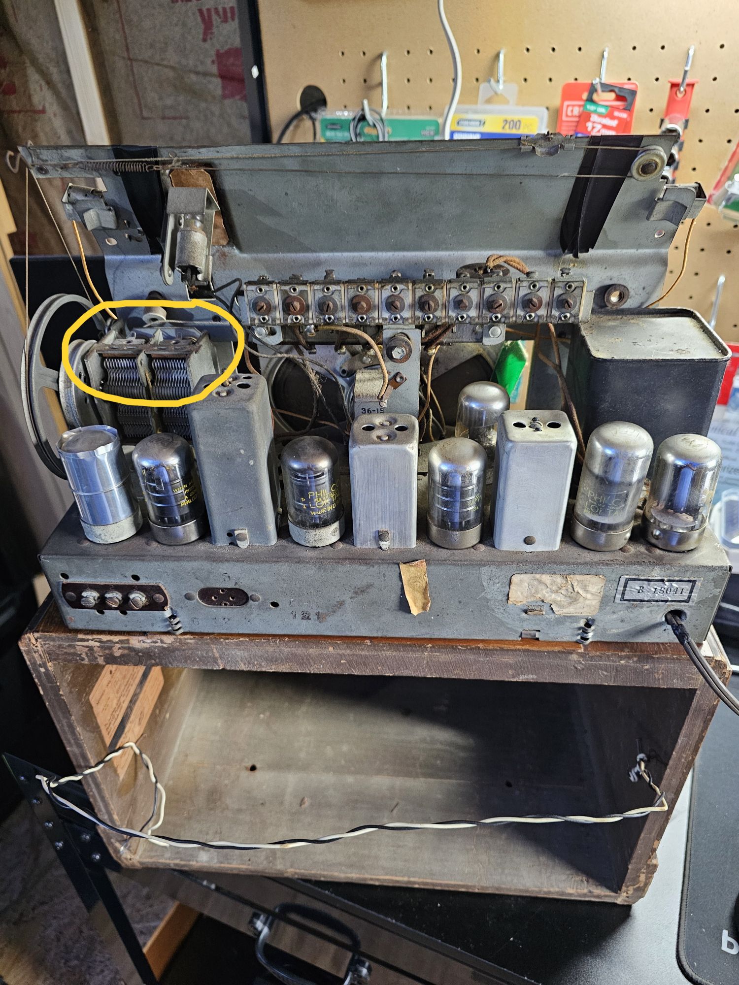
"Finally, a quick and dirty is to connect a long wire to the RF Stator of the tuning cap (make sure that your band switch is in the Broadcast, Manual Tuning (second) position."
I am still learning the Technical wording of parts of this radio, see the picture I attached and hopefully I am right in guessing it is the tuning cap? Also is one of the loops on top where I would connect the wire? Thanks
Posts: 2,327
Threads: 23
Joined: Jul 2020
City: Greenlawn
State, Province, Country: NY
Hi OSanders,
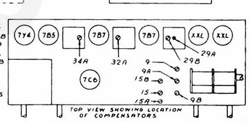
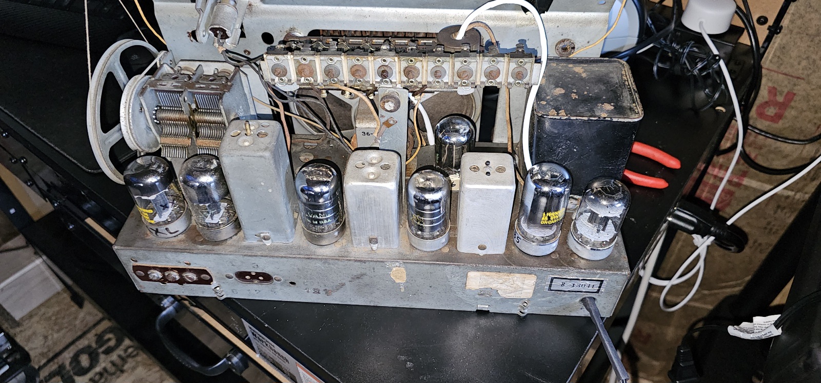
First off, apologies, I may have mixed up your case with Ken Aroyo's 52-942 However, 2 things. First, look at the 2 tubes on the leftmost side of the chassis, behind the tuning capacitor. They should both be 7A4s or XXLs. I can't tell what the first one is, as there is a shield over it. The second one is likely not an XXL. XXLs are triodes which have much smaller diameter plates than Pentodes like 7A7s or 7B7s or Pentagrid Convertors like a 7A8 in the picture, this tube looks like a 7A7.
One XXL is the local oscillator, the other one is the mixer. If you have a tube other than an XXL or 7A4 in either of these positions, all bets are off. If you put a 7A7 or 7B7 in the place of an XXL or 7A4, you won't smoke anything but it likely won't oscillate or mix. This configuration of a triode mixer and triode oscillator is rather unique in "modern" (1935 or later) sets. The other unique part is that this set has a 2 stage IF section. This is why some folks comment on how good this set is at "DXing". A pic of the tube layout is below:
The leftmost tube has a shield over it that looks homemade. For the shield to work, it has to be electrically connected to the metal base shell. Yours looks rather corroded. Clean the corrosion off with fine sandpaper unless you think that it is oxidized cadmium (Cadmium is quite toxic). The "LokTail" connects to a contact in the socket that is almost always grounded. You can also clean the tops of the tubes; the printing used for the tube type is quite stable. It's the printing on the side (the brand name) that tends to come off, even with water. I hold the tubes upside down when washing the top of the tube if I don't want to get the sides wet.
I happen to think that Loktal (or Loktail) tubes are of a good design. Yes, the pins are smaller than octal and older tubes, but so are the pins of the 7 and 9 pin miniature tubes. OK,maybe the sockets are an issue but thaqy can be cleaned.
Secondly, yes, touching a long wire to the terminal of the Mixer section of the tuning cap should allow you to tune a station if the oscillator is working. This is the part I meant for Ken's troubleshooting his set, but it could work for you. There are 2 sections to the tuning cap, the mixer / RF and the Oscillator. Usually, the oscillator section is the one closer to the shaft. touch a 25 foot or longer wire to the Mixer section of the cap. Ig you can now receive a signal, then troubleshoot the antenna section of the set. There are antenna coils and the "B" section of the band switch. The "A" Section controls the oscillator.
Hope this helps.
"Do Justly, love Mercy and walk humbly with your God"- Micah 6:8
"Let us begin to do good"- St. Francis
Best Regards,
MrFixr55
Posts: 63
Threads: 2
Joined: Mar 2025
City: Bristol
State, Province, Country: VA
Thank you MrFix55, Here is an updated picture of the tubes. The previous picture was from when I first started working on this set. The tubes were replaced over the weekend but still no longer receiving any broadcast so I'm going over the tips from you all.
Posts: 63
Threads: 2
Joined: Mar 2025
City: Bristol
State, Province, Country: VA
MrFixr55,
"If you have a tube other than an XXL or 7A4 in either of these positions, all bets are off."
Up until this past weekend all the tubes were as I received the set. The shielded tube looks possibly correct but the 2nd definitely is 7A7. Having a 7A7 in place of an XXL could that cause damage to the set?
Posts: 63
Threads: 2
Joined: Mar 2025
City: Bristol
State, Province, Country: VA
Thank you RodB, MirFixr55 and everyone else that provided support with the radio, I believe I've made progress.
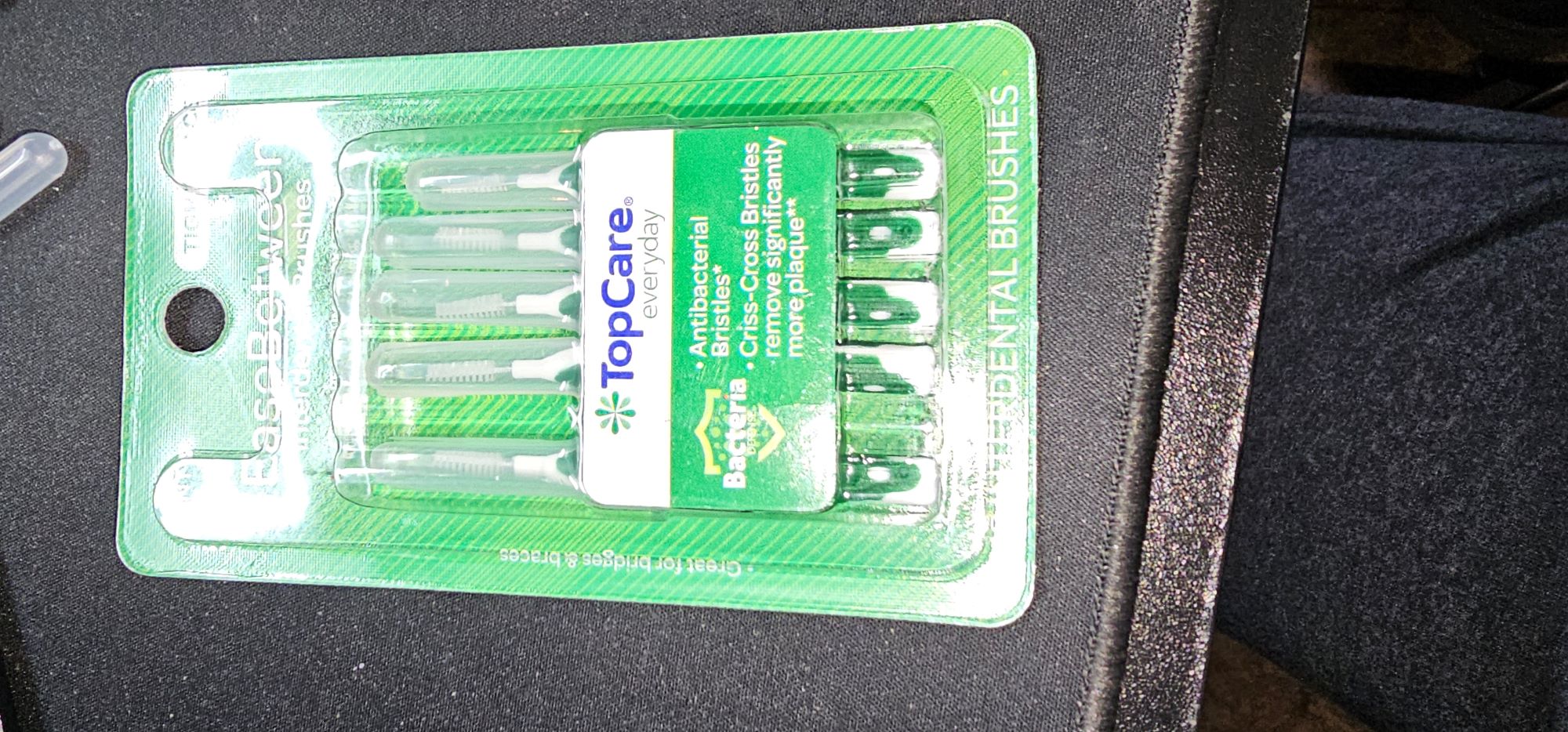
I think Rod mentioned cleaning the tube sockets and I read another thread about cleaning the tuning cap plates which I also did and to my surprise when I turned the radio on I was able to pull in a couple of stations before connecting the antenna. I cleaned with the DeoxIT and the brushes definitely were dirty after cleaning. I am still Leary about the band switch but I did turn the set off before switching to another band from broadcast and back and it still worked. Connecting the antenna pulls in even more stations.
Now putting it back into the case and hopefully it will continue to work, I will provide an update.
Posts: 63
Threads: 2
Joined: Mar 2025
City: Bristol
State, Province, Country: VA
It seems this radio has a mind of its own played about 3hrs. 2hrs in my shop and 1 at another location to test reception. I bring it back to the shop power up and nothing but static. I use MrFixr55 wire touch technique to the tuning cap (actually just placed near the cap location) and the stations start playing. I can turn it off and back on and for the most part it plays fine.
I can't see anything odd with the band switch, could this mean the oscillator is going bad?
Posts: 3,186
Threads: 226
Joined: May 2008
City: Omak
State, Province, Country: WA
Hello osanders0311,
I never thought of using those dental brushes.
glad you got it working .
on really dirty tuning capacitors I have been using my ultrasonic cleaner !
Sincerely Richard
Users browsing this thread: 2 Guest(s)
|
|
Recent Posts
|
|
Philco P45-6365 Universal Transformer Instruction Manual
|
| Can anyone guide me to where this may be found?GRG — 03:00 PM |
|
54C Complete Teardown/Rebuild
|
| I don't think that I have encountered a 12Z3 before, curious how it uses one of those but includes a #43, which is a 25 ...Arran — 02:17 PM |
|
HiFi (Chifi) tube amp build - but my own design.
|
| It's the other forum. I'm also in DIY, but mostly read there. Honestly, I kinda jumped into this without much thought to...TV MAN — 10:43 AM |
|
Philco 71 Code 125
|
| Hello,
I am in need of a schematic for this radio. Mine has the three separate circular tube shields and a shadow me...dconant — 08:06 AM |
|
Stromberg Carlson 1500 Squeal
|
| And life just keeps getting more complicated.dconant — 07:57 AM |
|
54C Complete Teardown/Rebuild
|
| Hello Roy,
here is this one
sincerely Richardradiorich — 12:45 AM |
|
54C Complete Teardown/Rebuild
|
| Richard,
Had grabbed it already but thank you just the same. I find myself wanting to find some way to block out the...glyphmon — 12:03 AM |
|
54C Complete Teardown/Rebuild
|
| Hello roy,
here is a link to the schematic .
Sincerely Richardradiorich — 11:54 PM |
|
54C Complete Teardown/Rebuild
|
| Richard,
The Silvertone 2014 also is a transformerless set, so I am incorporating a 1:1 600 ohm audio isolation transfo...glyphmon — 11:37 PM |
|
Preliminary work on wife's Silvertone 2014
|
| Did an alignment today which was interesting. IF alignment went great, almost all was already spot-on. Adjusting on th...glyphmon — 11:35 PM |
|
Who's Online
|
There are currently 1853 online users. [Complete List]
» 2 Member(s) | 1851 Guest(s)
|
|
|

|
 
|








