RCA 6K3 Preliminary Capacitor/Resistor Research
Posts: 172
Threads: 10
Joined: Mar 2026
City: Franklin
State, Province, Country: Maine
Arran,
All the paper capacitors have already been replaced. This was all just a hypothetical upgrade for when I get the whole unit back to as close to 100% as possible.
At the moment still trying to nail down the incorrect voltages going in to the 6A8 and 6K7 on pin 4.
Best wishes,
Roy
Posts: 5,653
Threads: 56
Joined: Sep 2008
City: Sandwick, BC, CA
Rob;
It won't be full B+, it will be higher then in regular operating mode, but still less then what it would be turning the set on from a standing start, at least in sets that have a directly heated rectifier like an #80. The biggest load on the B+ is still going to be the audio amp, and that will be run all the time, those will be running at a higher B+ with the front end tubes effectively out of circuit. People will often remove and replace tubes in a radio when attempting to troubleshoot a faulty stage, or a faulty tube, and 6.3 volt tubes usually heat up fairly quickly. The only sets I have heard of where that was a complete No-No was in a three way portable, because both the tube filaments, and the B+ is coming from the same source, and you can blow out one or more of the tube filaments.
If the cathode is no longer emitting electrons, then the plate and screen grids are really just sitting there doing nothing, I found this out with the Magic Eye in a Canadian RCA set, the B+ was cut off due to a faulty tube socket, so the target was a nice bright green, but the emission of the triode was borderline to weak because the heater remained lit any time the set was on. To be fair this set had a lot of hours on it, and at least three of the six tubes in the chassis were very weak, but generally magic eye triodes have good emission, but dim targets. It's basically the same problem you get with the picture tube in an instant on TV from the early 1970s, the cathode sits there cooking at a low voltage, but unlike in that RCA radio it's doing this as long as the set is plugged in.
Regards
Arran
Posts: 2,327
Threads: 23
Joined: Jul 2020
City: Greenlawn
State, Province, Country: NY
Hi Gliphmon,
Try replacing the resistor. With no load, the value at pin 4 of either socket should be very close to the B+ value at the other side of R4. Also make sure that the resistors that replaced the "Voltage divider are in the correct order. The Order s from the junction of the field coil, output transformer and c32, the resistors should be 3500 Ohms (R14), 13KOhm (R15) 85 Ohm (R16), chassis ground, 40 Ohm (R17), 175 Ohm (R18), HV Sec center tap.
You can use a DPDT switch to switch the audio between the external input and screw 1 of the phono terminal strip. The other pole of the switch can be set to short screw 1 to screw 3, shorting the output of the detector to ground.
Regarding shutting off the heaters, don't. There is a theory that putting B+ on tubes with the heaters off can shorten the tube life. I believe that running the filaments with no B+ is not only harmless but can rejuvenate the tube. Guitar amps and other high power industrial amps had an on/standby switch that would switch on or off the B+. The idea was to not turn the B+ on until after the tubes were heating for at least 30 seconds. In fact rectifier tubes were often designed to have a "controlled warmup to allow the other tubes to warm up before B+ was available. Many color sets of the 70s and 80s were mostly solid state had a small transformer for the CRT to keep the heater on. This was not just for "instant picture, the concept was that applying all the B voltages. especially the high voltage before the heaters were up to temp stripped the cathode and affected the emission of one or more guns. I have seen several color CRTs on sets without this feature, where one of the guns was dead, so a primary color was missing. This was rare on newer CRTs, possibly due to this feature, possibly due to better materials / manufacturing tevchniques. TV Man can chime in as he was a pro.
"Do Justly, love Mercy and walk humbly with your God"- Micah 6:8
"Let us begin to do good"- St. Francis
Best Regards,
MrFixr55
Posts: 172
Threads: 10
Joined: Mar 2026
City: Franklin
State, Province, Country: Maine
MrFixr55,
You nearly had me thinking I'd forgotten a step there when you included "chassis ground" in the order of the voltage dividing resistor. Yes, these are in the correct order, and I migrated and/or replaced one wire at a time when wiring the new assembly back in to ensure I didn't miss any, including the connection to chassis ground at that R16/R18 junction (not R16/R17). An aside, I'm not sure why they went R14 <-> R15 <-> R16 <-> R18 <-> R17, but it is marked as such on both the diagram and schematic, and so that is how I recreated it.
I'd need to place an order to get an actual 22K ohm. I have some 10K, 30K, and 50K on hand. For testing purposes, two 10K in series should be an acceptable test to see if there's a difference, right? The current R4 is testing at 21.1K out of circuit.
Edit/Update: I went ahead and tried two 10K in series, tested to 20.2K out of circuit, removed original, put in the two in series and no significant change. 64.6V on pin 4 instead of 63.5 off of 176V coming out of C16 (170V expected), so it looks like the original R4 was functioning approximately as intended at least. I think I'll put that one back in.
What do you make of the voltages I measured when pulling one/the other/both tubes? Even if it doesn't get us any closer to the answer, I'd be curious to know the implications of each.
With the 6A8 removed, the 6K7 showed 138.7V on pin 4, instead of 63.5 previously measured (100 expected).
With the 6K7 removed, the 6A8 showed 107.2V on pin 4, instead of 63.5 previously measured (100 expected).
With both 6A8 and 6K7 removed, the voltage on the tube-side of C15 and R4 is 218. I also went back to check and yes, same voltage on either side of the resistor in this case.
We can shelve the idea of switching power to the RF section for the time being. There's been a lot of good information shared and I will definitely refer back to this thread when we get to that point.
Best wishes,
Roy
(This post was last modified: 05-12-2026, 01:42 AM by glyphmon.)
Posts: 2,327
Threads: 23
Joined: Jul 2020
City: Greenlawn
State, Province, Country: NY
Hi Roy,
Yeah, I am scratching my head here. I assume that sensitivity and volume for this radio is low. I also assume that you have the radio hooked up to a long wire antenna and ground.
OK, for a little science:
Per the RCA receiving Tube Manual, the "Screen" Voltage for both tubes should be around 100V for a Plate voltage of 250V. The 6A8 Screen current at this voltage should be 2.7 mA. The Screen current for a 6K7 at this voltage is 1.7 mA for a total of 4.4 mA. Now if E=IR (Voltage = Current X Resistance) per Ohm's Law,
0.0044 Amp X 22,000 Ohm = 96.8 V voltage drop across the resistor R4. If the resistor is supplied with about 200V from the voltage divider, then the screen voltages should be about 103V
OK, with both tubes in, measure from Chassis ground to the side of R4 that connects to the Voltage divider junction between R14 and R15. Record that voltage. I expect that voltage to be about 200V +/- 20V. If significantly lower, then this must be investigated. Next, measure the voltage across R4. Record that voltage. I am expecting that you are going about 140V across that resistor instead of the 100V that I think that you should get if everything is working correctly.
Therefore, either there is something wrong with one of the tubes or something wrong with the biasing of these tubes. Grid voltage should be a negative number. With a weak or no signal, grid voltage should be about -3V. With a strong signal, grid voltage will be more negative due to the action of AVC (Automatic Volume Control). If you have spares, swap in a new 6A8 and 6K7.
Please post your results.
Good luck!
"Do Justly, love Mercy and walk humbly with your God"- Micah 6:8
"Let us begin to do good"- St. Francis
Best Regards,
MrFixr55
Posts: 172
Threads: 10
Joined: Mar 2026
City: Franklin
State, Province, Country: Maine
MrFixr55,
I do have a longish wire antenna attached but it's compacted for now, not strung out in a straight line, but I don't have a direct way at the moment to hook up a ground, unless we think running a wire into a ground prong at an outlet is sufficient.
The voltage at the R14/R15 junction with both tubes installed is 175 give or take. When the tubes were removed, this climbed to 218.
As I look at the schematic, maybe I'm wrong, but I think 170 is what's expected at that junction because that is what's specified in the tube voltage diagram as coming from C16, so I feel like 175 is pretty much okay for that side.
So, doing the same math, we need a 75V drop from what's present, or probably better to say a 70V drop from expected, which should mean a 15.9K (say 16K?) resistance? But the schematic, diagram, parts list, and resistors say 22K in both name and in testing. I could accept an error in the documentation, but I wouldn't think it would be consistent across all of them.
I don't have spare tubes, but I could order some. Though, maybe I'd find one or both of these in one of the other sets I haven't touched yet. Of course, they wouldn't be tested either. I'll take a peek to see what's in there in case I'm lucky. I presently have no other RCA radios so they will at least probably be a different brand if the same tube type. Edit: The 37-620 sitting right next to it has a glass 6A8 and a 6K7MGT which was lucky. The readings changed slightly - up to 66V on pin 4 and 173 on R14/R15 junction. Not enough to make me think that this is the root issue. I cannot of course vouch that these two other tubes are 100% good, but only that the last person who worked on it before me put the 6K7MGT in (as it is a newer Realistic brand that was not in the radio when I first took it to be serviced), and I would hope he verified the other tubes while he was at it.
As far as sensitivity and quietness, it's hard for me to judge. I managed to tune in only one AM station from about 15 miles away. The next closest is about 28 miles away, and from there is Boston at over 200. On shortwave, I could receive from Romania enough for my wife to understand what was being said, and there were other stations I've come across at different times. There is much more activity on shortwave, or at least more points on the dial where it sounds like the radio is picking something up. The volume hasn't been especially quiet, though I don't know that I had to turn it up to max. Certainly when I used my AM transmitter in the same room it was plenty loud without max volume.
Best wishes,
Roy
(This post was last modified: 05-12-2026, 11:12 AM by glyphmon.)
Posts: 1,797
Threads: 55
Joined: Feb 2015
City: Roseville, MN
Hi Roy,
I'm following you on the schematic for the 170 volts to the 6A8 (C16). That would be pretty much spot on. When measuring these voltages try to keep in mind that the calculated values are definitely off from what you see on the schematic. That is the paradox Mr. Sarnoff's design engineers were placed in. Test volt meters of the day for repair technicians amounted to 1000 ohms per volt. Test equipment for design labs probably 20,000 or better. The field tester values are what you are seeing on the schematic because Mr. Sarnoff, in spite of reputation, opted to use reality over science. Hence, the spiel you read here a couple days ago regarding shunts and special meters, yata, yata, yata... Today you hold a scientific/reality instrument in your hand and there's no fuzzy edge from it.
Now, I'll get down from the soap box. I lost you when you mentioned the 70 volt drop. I followed the voltage at C16 and it runs through L7 and L11 to get the oscillator primary excited, then on to the oscillator plate, 5 volt drop. I assume your reference to the 70 volt drop is somewhere in the power supply voltage divider. Or perhaps the 6A8 screen grid voltage.
PS I'm glad you have reception good enough to get your spouse involved. Romania is indeed a rarity in my neck of the woods.
(This post was last modified: 05-12-2026, 12:37 PM by RodB.)
Posts: 172
Threads: 10
Joined: Mar 2026
City: Franklin
State, Province, Country: Maine
Rod,
Here's where I'm at:
Pin 4 on both 6A8 and 6K7 are, according to the tube voltage diagram, supposed to test at 100V. They are connected so naturally they will test the same.
Actual results for these pins are from a low of 61ish to a high of 66ish with tubes swapped for others from the other set I've worked on recently.
With tubes in, I show 172-176V everywhere from the junction of R14/R15, to C16, to pin 6 of the 6A8. On the back side of R4 (side opposite the connection to the tubes) likewise.
Across R4 however, toward the tubes, we're seeing the 61-66 referenced above, depending on the test and conditions, so roughly a 110V drop from one side of R4 to the other. If I'm correct in my understanding, if the tubes are supposed to be showing 100V on pin 4, then the near side of R4 should be 100V, a drop of 70V from what is supposed to be on the far side, 170V, and a drop of 72-76V from what I'm getting for my readings.
The resistor is in fact a 22K resistor, I have swapped it for two 10K resistors in series since I don't have a spare 22K on hand. Both the pair and the original test close to their anticipated values. The diagrams/schematics specify 22K, so it seems like it is the intended part and is functioning as it should.
MrFixr55 provided current values for the tubes that suggested to get 100V at pin 4 across a 22K resistor, we expect 200V give or take at R14/15 which to me says, everywhere it's presently reading 175 or so, which doesn't seem to add up either. In saying that, I'm not suggesting he or his information is wrong either, but this is a case where I'd say the math isn't mathing. Changing the resistor didn't change the readings, neither did swapping tubes from another set, though I could just be lucky and have two sets of equivalent tubes that are both bad in the same way, though I think it's unlikely as well.
Perhaps not a silly question, but not knowing how it would affect anything else along the way, if we assume that the current that MrFixr55 found/calculated is correct, that it's 0.0044 amps, would a 16K (or thereabout) resistor work to drop the voltage from approximately 170 volts on the far side of R4 to about 100 on the near side and pins 4 on both the 6A8 and 6K7? If so, that would get us within spitting distance of the anticipated value, but would be a deviation from the design and components actually in place.
Is there anything else in this part of the circuit that would be impacting what I guess is the screen grid voltage (pins 4)? Everything else is, from what I've heard so far, reasonably close to where it's supposed to be. Capacitors are new. Resistors test within spec of have been replaced, including the entire voltage dividing resistor.
The radio runs, but if it can run better, I'm game, but I'm way out of my depth with this rabbit hole.
Best wishes,
Roy
Posts: 1,797
Threads: 55
Joined: Feb 2015
City: Roseville, MN
OK, got it. I looked at the typical screen current for the two tubes and 2.5 ma should be the max. Your measurement of 110 volts across 22k is a fuzzy 5 ma, which is max for a half watt resistor (should be quite warm). This should have around a 60 volt drop, so something is causing more current than required to flow through it. First thing I would do is disconnect and/or replace C15. Monitor the voltage drop after doing that. Be sure the solder joints are good. Look for anything in the wiring that may affect the connections. I don't believe it would cause the symptoms but maybe the tube socket pins need cleaning. The drop across R4 s/b around 35 volts with the 6K7 out and around 25 volts with the 6A8 out. I'm trying to think of other things that may do this or ways to eliminate things.
Posts: 1,797
Threads: 55
Joined: Feb 2015
City: Roseville, MN
There should be 0 volts across R4 with both tubes out. (I'm pretty sure, anyway. )
Posts: 2,327
Threads: 23
Joined: Jul 2020
City: Greenlawn
State, Province, Country: NY
I would agree that the voltage drop across R4 should be 0V with both tubes out if C15 is good. Since the DC ripple at that point should be very low, the cap should not draw current, like the filter caps would.
This is a stab in the dark. since you get a strong signal out of your AM transmitter, tune that in (with an audio program) and measure the voltage at pin 4 of either the Convertor or IF tube. If you have a strong signal, the grid bias should be much more negative than with no signal received. This may change the current draw of the tube and may raise the voltage. It would be interesting to see the results of this test. The problem is that the published conditions in the Service Notes (from Rider) are no signal and volume control at minimum. However, I would still do the testing.
My calculations in the previous post are based on specs in the RCA Receiving Tube Manual, version RC13, published in 1940. Attached below are the associated pages:
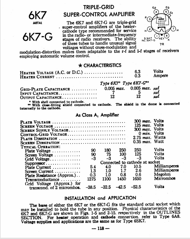
My theory for the supply voltage to R4 was based on the total resistance from B+ (junction of speaker voice coil) to chassis ground (16585 Ohm), the ratio of the resistance from B+ to the supply side of R4 (3500 Ohm) to the total voltage divider resistance from B+ to Chassis Ground (16585 Ohm) being about 21% and if the supply voltage to the divider is 250V, than a 20% drop would be 50V, therefore R4 is supplied by 200V (I did not take current draw for these 2 tubes into the equation as I expected the current through the divider due to its own resistance to be rather high.)
"Do Justly, love Mercy and walk humbly with your God"- Micah 6:8
"Let us begin to do good"- St. Francis
Best Regards,
MrFixr55
Posts: 5,653
Threads: 56
Joined: Sep 2008
City: Sandwick, BC, CA
If running tubes with the heaters on, but with no B+ is harmless, then why is it that in any AM/FM set I have encountered, where they use an FM tuner, and the tubes in that tuner have the B+ switched off, are the tubes almost stone cold dead emissions wise? These were in sets where the tubes were all seemingly original, assuming that the tubes were not all replaced at some point, and the tubes used for the AM broadcast, and shortwave bands were all functional. In fact it was suggested in at least one magazine article I read that it would be best to operate such tubes with a reduced B+ voltage, via a resistor, then to switch it off altogether.
I'm not sure where that theory came from that having plate voltage on a tube with the tube heater off would damage the tube, the flow of electrons from the cathode ceases, but there is really nothing stopping one from switching both the B+ and heaters off. Again the front end tubes are not the main current hogs in the radio, the main current draw would be from the tube heaters, approximately 300 ma each, the B+ is in tens of milliamps.
Getting back to the Bluetooth modules, the fellow behind the Electronics Old and New channel often adds these to his German sets, but he pairs them up with a power supply model, tapping voltage off the heater circuits. Basically he uses the tape or phono switching circuits to connect the Blue Tooth, something most German radios have. I'm linking to his odysee channel here, I think Y.T is getting enough traffic they don't deserve: https://odysee.com/@ElectronicsOldandNew:c?view=content
Regards
Arran
Posts: 172
Threads: 10
Joined: Mar 2026
City: Franklin
State, Province, Country: Maine
Okay, this isn't an update, but a summary of what I need to do next by my reading of Rod's post:
Desolder C15, test voltage on both sides of R4 (with both tubes in?)
Test voltage on both sides of R4 with 6A8 removed only (with C15 reinstalled or still out?)
Test voltage on both sides of R4 with 6K7 removed only (with C15 reinstalled or still out?)
Test voltage on both sides of R4 with both tubes out (with C15 reinstalled or still out?)
Also, for informational reference, test pins under load as tuned to AM transmitter (not test conditions specified by manufacturer)
Rod, please let me know if any of this understanding is incorrect.
C15 is new from my recapping, so if it's not working it's either a bad cap out of the box, or poor soldering on my part.
I won't be able to do this troubleshooting for a couple days as my soldering iron decided to not want to get hot tonight so if my understanding of your suggestion is wrong, you've got a little time to let me know. If any other thoughts come up for things to test, feel free to chime in while I'm waiting for the replacement iron to come in.
Thank you and MrFixr55 for your diligence in helping me chase down this gremlin.
Best wishes,
Roy
(This post was last modified: 05-13-2026, 10:25 AM by glyphmon.)
Posts: 2,327
Threads: 23
Joined: Jul 2020
City: Greenlawn
State, Province, Country: NY
Hi Roy,
Before desoldering, try measuring the Screen (Pin 4) voltages while receiving a signal from your AM transmitter. This should cause a high negative AVC voltage which should lower tube current. This will be an interesting piece of info.
"Do Justly, love Mercy and walk humbly with your God"- Micah 6:8
"Let us begin to do good"- St. Francis
Best Regards,
MrFixr55
Posts: 172
Threads: 10
Joined: Mar 2026
City: Franklin
State, Province, Country: Maine
After a bit of hiatus, I'm back with just a tidbit of information. I only had the time to get R4 soldered back into place tonight and test things with tubes in, tuned to my AM transmitter, but also separately just with the antenna disconnected. I may be completely off on this but I figured, if the goal is tuned to dead air with volume down, what's deader than no antenna?
First, with the antenna disconnected, the voltages were the same as before - approx 63V on pins 4.
With the antenna reconnected, tubes in, and tuned to my AM transmitter with volume high enough to reasonably fill my small room but not loud enough to wake my wife (I hope) pins 4 tested at 91V. Across R4, coming from the voltage-dividing resistor tested at 187V, up from the typical 175V.
What are the implications of this result, would you say?
I will try to do the other tests mentioned (below) this weekend. Can we confirm if C15 is supposed to be removed or in place for the following:
Test voltage on both sides of R4 with 6A8 removed only
Test voltage on both sides of R4 with 6K7 removed only
Test voltage on both sides of R4 with both tubes out
Since I've already tested them with C15 in place, I would expect this time we should test with it removed? And to confirm, in doing so, that connection to chassis ground should be completely open for this test?
Best wishes,
Roy
Users browsing this thread: 48 Guest(s)
|
|
Recent Posts
|
|
Plug Voltages Needed For A 1943 CRV-20130 Power Supply
|
| hello david,
I have a similar generator in my collection that features a cast iron, single-cylinder Briggs & Stratt...radiorich — 01:00 AM |
|
under chassis parts locator diagram for 1938 Zenith 9s262
|
| Has anyone gone to the trouble of creating an under chassis parts locator image? Yes, I can identify components by foll...bobloney — 08:57 PM |
|
Plug Voltages Needed For A 1943 CRV-20130 Power Supply
|
| Try looking at this site the book mark is for a old generator that I was given. David https://radionerds.com/index.ph...David — 08:36 PM |
|
Plug Voltages Needed For A 1943 CRV-20130 Power Supply
|
| Hello Everyone,
I am looking for voltage identification for all the pin positions on the socket of a CRV-20130 power su...Tonym4704 — 08:16 PM |
|
Philco P45-6365 Universal Transformer Instruction Manual
|
| Can anyone guide me to where this may be found?GRG — 03:00 PM |
|
54C Complete Teardown/Rebuild
|
| I don't think that I have encountered a 12Z3 before, curious how it uses one of those but includes a #43, which is a 25 ...Arran — 02:17 PM |
|
HiFi (Chifi) tube amp build - but my own design.
|
| It's the other forum. I'm also in DIY, but mostly read there. Honestly, I kinda jumped into this without much thought to...TV MAN — 10:43 AM |
|
Philco 71 Code 125
|
| Hello,
I am in need of a schematic for this radio. Mine has the three separate circular tube shields and a shadow me...dconant — 08:06 AM |
|
Stromberg Carlson 1500 Squeal
|
| And life just keeps getting more complicated.dconant — 07:57 AM |
|
54C Complete Teardown/Rebuild
|
| Hello Roy,
here is this one
sincerely Richardradiorich — 12:45 AM |
|
Who's Online
|
There are currently 1943 online users. [Complete List]
» 1 Member(s) | 1942 Guest(s)
|
|
|

|
 
|







