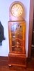
1953 Philco 53-T1886 Code 125 AM/FM/Phono/TV Combo
Posts: 1,797
Threads: 55
Joined: Feb 2015
City: Roseville, MN
Are these capacitors in voltage doubler circuits? Let's say you need 8mfd at 1000 volts. You can put two 16mfd 500 volt caps in series to get it. The capacitance is halved and the voltage is doubled. You can't get something for nothing.
Posts: 374
Threads: 41
Joined: Dec 2019
City: Elkhart
State, Province, Country: Indiana
Quote:Are these capacitors in voltage doubler circuits? Let's say you need 8mfd at 1000 volts. You can put two 16mfd 500 volt caps in series to get it. The capacitance is halved and the voltage is doubled. You can't get something for nothing.
I have no idea where these capacitors are in the TV's circuit or what purpose they serve as I just saw them in the Capacitor Parts Listing in the Sam's Photofact for the TV, I really didn't take a look at the schematics to see where those capacitors were in the Circuit and what purpose they were serving.
I unfortunately have a physical copy of the Sam's Photofact for this TV so I don't really have any way to upload the schematics on here very easily because I don't have a scanner that's big enough to scan the schematics page into the computer, and trying to use the camera on my phone wouldn't work very well because it wouldn't be able to blow the schematics up large enough to be readable on the computer screen without distorting them.
How would I tell if the capacitors I had mentioned were in a voltage doubler type circuit or if it was just being used to filter the high voltage circuits?
UPDATE: I looked at the schematics and looked up those capacitors on the schematics and they were actually High Voltage Ceramic Disc Capacitors, and from what I saw in the parts list vs. the schematics for those capacitors is that the way they marked those capacitors in the parts list compared to the rest of the mica or ceramic disc capacitors is that the majority of the ceramic disc and mica capacitors in the parts list didn't have a voltage listed with the capacitance value, but then there was a few ceramic disc capacitors that were listed with a voltage value on the parts list which made me think they were electrolytic capacitors because they listed the capacitance values in whole numbers rather than decimal values like the paper capacitors were which are listed with a voltage value and electrolytic capacitors are usually listed with a whole number value and a voltage value which is why those capacitors in the parts list threw me for a loop.
So it turns out I have a lot less capacitors to order than I thought I did initially, according to my parts list count I have 41 film capacitors I will need to order to replace these old Bumblebee paper capacitors with, and 11 electrolytic capacitors for a grand total of 52 capacitors all together.
Posts: 1,369
Threads: 94
Joined: Jan 2014
City: Annapolis, IL
State, Province, Country: USA
RodB is dead on putting caps in series if you need higher voltages,. Many OEM setups are already that way esp in doubler circuits and amps that use higher than 500v in the B+. The ceramic HV caps should be ok, but if you do end up needing something, Just radios (Canada) has a lot of HV caps. Both tubular and disc. I've used them in restoring electrostatic sets. Just remember, take lots of close pictures, notes and I really urge you on doing a section at a time - test, then move on. Also, I don't remember if I mentioned leaving the brightness down when you test in case the vertical is dead so you don't burn a line across your picture tube. Sneak it up very carefully and listen too since you can hear the vertical running (or not). You may also be able to hear the horizontal section start up, although some people cannot hear it. If in doubt about something, you can snap a picture of the section of the schematic in question, and post, such as the power supply or horizontal sweep section.
If I could find the place called "Somewhere", I could find "Anything" 
Tim
Jesus cried out and said, "Whoever believes in me , believes not in me but in him who sent me" John 12:44
Posts: 18,427
Threads: 622
Joined: Oct 2011
City: Jackson
State, Province, Country: NJ
Putting together number of caps of the same value:
Serializing of N capacitors:
- Divides the capacitance by N.
- Multiplies the WV by N.
Example: 3 caps of 1uF 500V in series will result in 0.33uF 1500V.
Paralleling of N capacitors:
- Leaves the WV the same.
- Multiplies the capacitance by N.
Example: 3 caps of 1uF 500V in parallel will result in 3uF 500V.
Now. When serializing, ESPECIALLY electrolytics (which are nown for their higher than the rest's leakage current) the equalizing resistors need to be used.
Each capacitor receives a resistor across it that should conduct the current that is about an order of magnitude higher than the leakage current.
If not put in places, the voltages across the capacitors may differ significantly, and if close enough to WV, one of the caps could receive the voltage across it that exceeds the WV.
Example: serializing 2x22uF 500V electrolytics.
A theoretical leakage acrdoss such a cap using the formula I=0.01*C*V is 100uA at 500V.
So we want the resistors that would result in 1mA of current.
This would be 500K across each cap. The power dissipated woul be 0.5W which is a bit excessive, so we could go higher in resistance, considering a healthy cap has much lower leakage.
Let's have 300uA.
The resistance is 1.7M.
The dissipation is 0.15W.
So, each capacitor of 22uF will receive a 1.7M resistor across it.
PS. Non-electrolytic caps have very low leakage and we do not have to worry about it.
People who do not drink, do not smoke, do not eat red meat will one day feel really stupid lying there and dying from nothing.
Posts: 374
Threads: 41
Joined: Dec 2019
City: Elkhart
State, Province, Country: Indiana
An Update on this set: I started replacing the capacitors on this set last week, and as I suspected the Radio chassis was super easy, I replaced all but one of the capacitors because one of the capacitors was attached across a wafer switch assembly and I didn't want to risk damaging the wafer switch, so I left it alone (also it wasn't in a super critical section of the circuit.) Working on the the TV Tuner/IF and RF section now.
Posts: 2,327
Threads: 23
Joined: Jul 2020
City: Greenlawn
State, Province, Country: NY
I hear you regarding diddling the IF transformers. I ruined an off the street Emerson version of an RCA CTC7 trying to diddle out the worms in the picture. The set was hooked up to cable, without a converter. It did not dawn on me that Analog TVs back then were not designed to receive adjacent channels. Other than Channel 4 and 5 where there was sufficient space, no geographic area had adjacent stations, such as having active stations on Channels 2,3, 4, 5, 6, etc. TVs back then did not have the ability to tune sufficiently sharply to reject the adjacent channels.
"Do Justly, love Mercy and walk humbly with your God"- Micah 6:8
"Let us begin to do good"- St. Francis
Best Regards,
MrFixr55
Posts: 1,369
Threads: 94
Joined: Jan 2014
City: Annapolis, IL
State, Province, Country: USA
Also keep in mind there's a lot of 'junk' in the newer video signals that may show up on an older set making you think there's something wrong with your set when it's fine. Mostly the copy protection they put on everything so you don't record it, sell it and retire off all your profits lol. But seriously, there's so much interference that the older sets can pick up that the 'newer' sets filter out, these LED light bulbs, computers, chargers, oh - 'flagging' on VCR tapes, looks like the H sweep is trying to go out of sync. So again, if you see something like that, think outside the box, literally. Also, keep in mind that the newer video format will look like shrunken vertical on an older set, so don't go cranking up the vertical height to try to eliminate it, you'll drain the life out of your output tube and maybe even your output trans.
If I could find the place called "Somewhere", I could find "Anything"
Tim
Jesus cried out and said, "Whoever believes in me , believes not in me but in him who sent me" John 12:44
Users browsing this thread: 1 Guest(s)
|
|
Recent Posts
|
|
Philco 45-6365 Universal IFT Instruction Manual
|
| The Philco Parts Catalog for 1942 shows it as usable for 175 kHz, 260 kHz, and 465 kHz. The instructions will show how t...DaleHCook — 11:19 AM |
|
Stromberg Carlson 1500 Squeal
|
| Hello Rob,
I agree with you—I have one here at my house that I need to check out. It’s way over-engineered just to make...radiorich — 11:05 AM |
|
My Atwater Kent 84
|
| Well getting around to restoring my AK84. Mike was a big part in me being able to snatch this one a few years ago. I won...462ron — 10:57 AM |
|
Plug Voltages Needed For A 1943 CRV-20130 Power Supply
|
| The engine is a B&S 23 inch cast Iron holds 2 quarts of oil. The Generator is a 4 pole 1800 rpm mine was made in 195...David — 10:51 AM |
|
Philco 45-6365 Universal IFT Instruction Manual
|
| Dale: Modified topic as suggested. It is not for a specific project. I found it in a box of stuff I recently purchased...GRG — 10:34 AM |
|
Plug Voltages Needed For A 1943 CRV-20130 Power Supply
|
|
That looks a lot like an aircraft connector of some kind ...
That is a MIL-5015 style connector, used in a wide v...DaleHCook — 10:19 AM |
|
Philco P45-6365 Universal Transformer Instruction Manual
|
| I would suggest changing the topic from "P45-6365 Universal Transformer" to "45-6365 Universal IFT."...DaleHCook — 10:08 AM |
|
Stromberg Carlson 1500 Squeal
|
| And life just keeps getting more complicated. By dconant.
Dittos'Jimradio — 08:01 AM |
|
Plug Voltages Needed For A 1943 CRV-20130 Power Supply
|
| That looks a lot like an aircraft connector of some kind, even if it's a U.S.N power supply. I have a book somewhere abo...Arran — 02:56 AM |
|
Plug Voltages Needed For A 1943 CRV-20130 Power Supply
|
| hello david,
I have a similar generator in my collection that features a cast iron, single-cylinder Briggs & Stratt...radiorich — 01:00 AM |
|
Who's Online
|
There are currently 1362 online users. [Complete List]
» 1 Member(s) | 1361 Guest(s)
|
|
|

|
 
|