Posts: 16,495
Threads: 573
Joined: Oct 2011
City: Jackson
State, Province, Country: NJ
Wanted to pick your brains, guys.
The radio came.
Yes cosmetically it is very good and the chassis seems to be OK.
When taking the radio out of the box (packed real well) I heard some banging....I looked inside when I unpacked it; the speaker was loose.
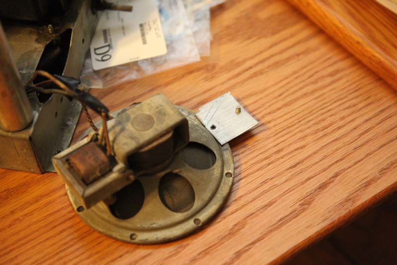
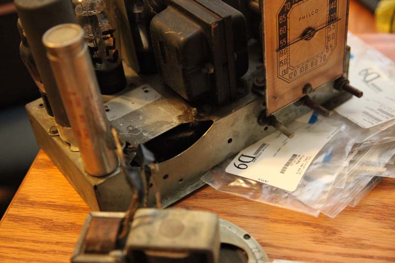
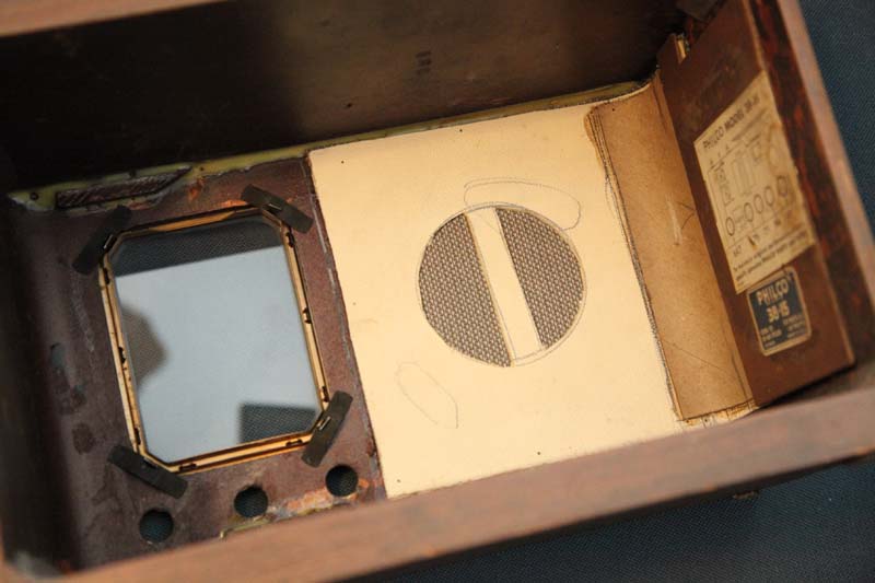
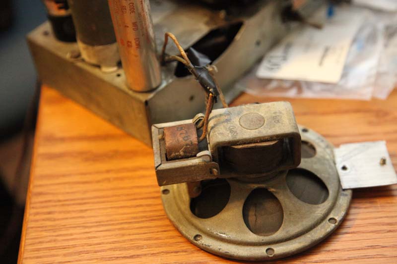
But that'd be OK as long as it did not destroy anything (which it seemingly did not, or at least I do not see any damage); the problem is, the radio was obviously a subject to someone attempt to restore it (which we knew from Ron's comments) and the grillcloth was stretched over a solid piece of something, with no slits or a hole for the speaker, and the speaker is not bolted to anything at all.
My guess is, the restorer relied on the speaker to remain in a tilted position (it is propped up by the power tranny) for the sound to move in front of the cone; otherwise it would be a problem.
So, should I let it go or do you think that will be too much work to do? The cloth is stretched over some bending radius, so it is not as simple as simply stretching it over a rectangular board.
What do you guys think?
Again, it looks beautiful otherwise; the question is how much trouble it is to re-mount the speaker (if it survived the shipping of course - to test it now is not that easy).
Posts: 4,435
Threads: 419
Joined: Jun 2011
City: Boston
State, Province, Country: Massachusetts
Any pic's?
Paul
Tubetalk1
Posts: 16,495
Threads: 573
Joined: Oct 2011
City: Jackson
State, Province, Country: NJ
Paul
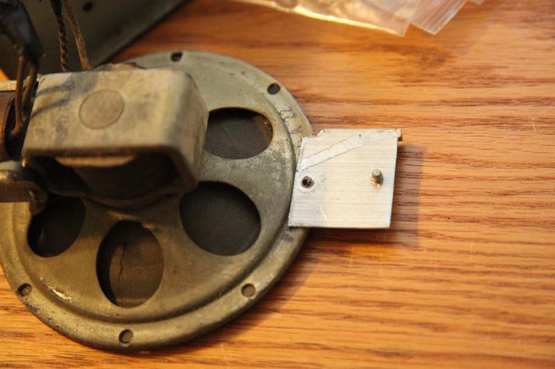
Here are the pics.
Obviously the opening is there, but the speaker is secured to the chassis (sort of like in portable radios) and not to the cabinet.
But it is possible the speaker is no original, so the make-shift bracket was concocted from a piece of aluminum, and the screws are short and during the transportation they just let go.
Posts: 16,495
Threads: 573
Joined: Oct 2011
City: Jackson
State, Province, Country: NJ
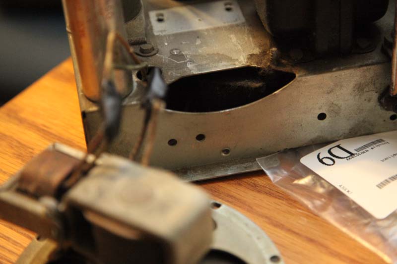
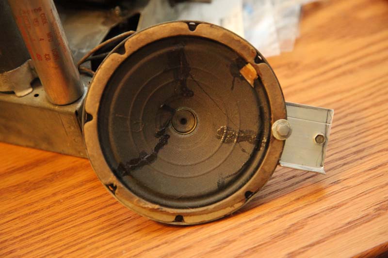
More pics:
The speaker of course was repaired for multiple tears.
Posts: 13,776
Threads: 580
Joined: Sep 2005
City: Ferdinand
State, Province, Country: Indiana
Your speaker is definitely not original.
[Image: http://i326.photobucket.com/albums/k420/...27760f.jpg]
See where a bracket was once fastened on the chassis behind the speaker? This bracket was fastened to the original speaker.
[Image: http://i326.photobucket.com/albums/k420/...f5a6f4.jpg]
Yup, that's a homemade bracket on the front of that speaker. The original had a bracket here, also.
Looks like you need a speaker. You can use one from either a 38-15 or a 38-12, as the field coils have the same resistance.
--
Ron Ramirez
Ferdinand IN
Posts: 16,495
Threads: 573
Joined: Oct 2011
City: Jackson
State, Province, Country: NJ
thanks Ron.
yes I realized it is not original, otherwise there'd be no makeshift brackets.
I could probably fix the radio using this one, and then try to buy a genuine one.
What I want to hear is, in your opinion, do you think it's worth it?
Posts: 16,495
Threads: 573
Joined: Oct 2011
City: Jackson
State, Province, Country: NJ
Just went to look for Philco speakers: Ebay has some, but of course not mine.
If anyone knows of any that Ron pointed, please keep me in mind.
Posts: 4,435
Threads: 419
Joined: Jun 2011
City: Boston
State, Province, Country: Massachusetts
Morzh-
Maybe Jeffrey G has one, if not posted for sale you can ask, he has parts, a lot of parts.
http://radiotiques.com/forsale.asp?Tab=Tube
Good luck....
Pablo
Tubetalk1
Posts: 16,495
Threads: 573
Joined: Oct 2011
City: Jackson
State, Province, Country: NJ
Thanks, Paul
I did not even know this place.
I will sure ask.
Mike.
Posts: 13,776
Threads: 580
Joined: Sep 2005
City: Ferdinand
State, Province, Country: Indiana
morzh Wrote:What I want to hear is, in your opinion, do you think it's worth it?
Yes, I think so. The cabinet looks much better than most, and the dial scale (which is quite fragile because of the foil) looks very nice.
Here are a couple more Philco models that have speakers which will work: 39-6, 39-7. The field coils in these are 1700 ohms instead of the 1500 ohm field used in the 38-12 and 38-15 speakers - close enough. The higher field will just drop your B+ a little bit, not necessarily a bad thing.
--
Ron Ramirez
Ferdinand IN
Posts: 16,495
Threads: 573
Joined: Oct 2011
City: Jackson
State, Province, Country: NJ
Thanks Ron, I was also leaning towards keeping it.
Worst case I will make it work with the existing speaker and then will be looking for the original one in the background.
Posts: 4,875
Threads: 54
Joined: Sep 2008
City: Sandwick, BC, CA
I would make do with the speaker that's in there, but perhaps come up with a more secure way of mounting it. It looks a bit like a Utah made speaker from the 1950s or so, a lot of parts catalogs from the 1940s through the 60s used to carry Utah replacement speakers.
Regards
Arran
Posts: 16,495
Threads: 573
Joined: Oct 2011
City: Jackson
State, Province, Country: NJ
Thanks Arran,
I could try that too.
As I stated many times, I am not too good with anything that involves drilling, hammering, winding or such. The soldering is the exception - I am very good with it, despite my shaky hands. 
So I need to see if making a better mount is something that an inept mechanical ignoramus like myself can take care of or if it is something that is beyond my wildest imagination and is akin to making a rocket engine for a real spacecraft.
In which case it is easier for me to shell some dough provided the merchandize does exist anywhere at all and within my disposable income and can be safely concealed from my ol'lady  

Posts: 16,495
Threads: 573
Joined: Oct 2011
City: Jackson
State, Province, Country: NJ
Sorry.
I posted here something that belongs to another thread, the WR-212.
Posts: 16,495
Threads: 573
Joined: Oct 2011
City: Jackson
State, Province, Country: NJ
OK, so now that I am more or less done with the 18, I eventually got back to this one.
This is the sch.
http://www.nostalgiaair.org/PagesByModel...013239.pdf
Took some pics of the underbelly.
The set was repaired at some point and that point was probably when I was..well, not in diapers - we did not have diapers, but as we say when I was able to walk under the dinner table without stooping, which I think translates as knee-high to a grasshopper. 
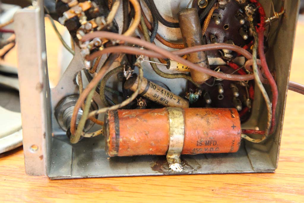
It was done fairly neatly - the "new" cap is secured with a tin band soldered to the chassis (I thought the chassis was aluminum but soldering indicates otherwise, probably steel).
You can see a cut wire from the original cap, which was not removed.
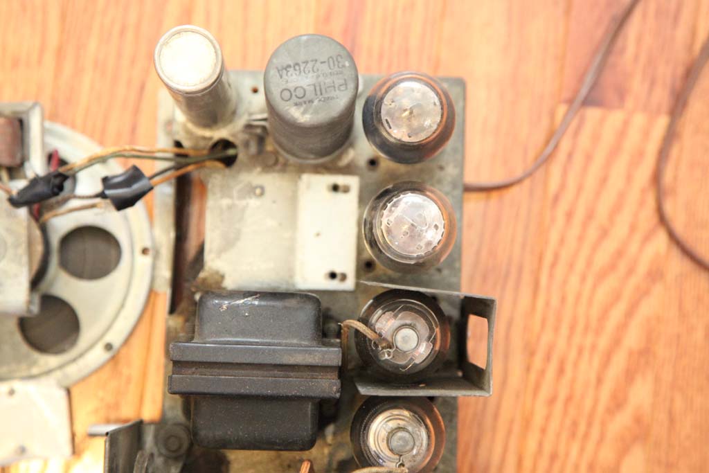
It's the grey cap at the top-center of the chassis.
It is 16uF and not 12uF like it should be, but I guess that much deviation is OK.
Oh! Is it me, or did Philco connect the capacitors across the power cord without discharge path? Granted, it is 5nF equivalent but it will give you a painful pinch if touched after it was extracted from the outlet during the peak voltage.
Since it is a RPITB to re-rout it I intend to introduce a 1M resistor just across. The caps need changing anyway, the only backelite block in the whole set. The rest seem to be the tubulars. They all marked as PHILCO so I intend to keep the shells to hide the yellow.
OK! Good luck to me!
Users browsing this thread: 1 Guest(s)
|
|
Recent Posts
|
|
Road Trip for a Philco 46-480
|
| Good morning, folks! I’ve finished the cabinet and the electrical restoration, and have detailed those in their respecti...jrblasde — 10:56 AM |
|
Studebaker/Philco AC-2687 car radio
|
| Arran,
Thanks for checking you manuals.
I appreciate that. Let me know what you find.
PhilPdouglaski — 08:46 AM |
|
Studebaker/Philco AC-2687 car radio
|
| I have some car radio service manuals, Riders I think (not to be confused with the big blue binders), so I may see if on...Arran — 01:20 AM |
|
Philco model 40-100
|
| Greetings;
Here is an update, I found a listing on fleabay for a similar chassis to yours, and it has a photo of what...Arran — 12:58 AM |
|
Philco model 40-100
|
| Greetings;
I think I may have found a clue as to what is missing, from a search I made, there is a rear view of the c...Arran — 12:12 AM |
|
Philco model 40-100
|
| I recently acquired a Philco model 40-100 farm (battery) radio. The radio was in very good condition except the red on f...mhamby — 05:59 PM |
|
Studebaker/Philco AC-2687 car radio
|
| Hello, Richard
the radio is an AC-2687 Studebaker model. The Philco model is S -5323 and the chassis p/n is S-5523Pdouglaski — 11:52 AM |
|
48-482 rear panel help
|
| The 48-482 is an AC only set as well, featuring a power transformer. While the transformer shouldn’t get “hot”, it is ye...jrblasde — 11:12 AM |
|
Studebaker/Philco AC-2687 car radio
|
| I gave a Chrysler/MoPar car radio from 1954, it was made by Philco, and it uses two chassis, one has the power supply an...Arran — 11:06 AM |
|
48-482 rear panel help
|
| Hello keithchip. You could make a hardboard back for the set, but make sure you provide plenty of ventilation holes in ...GarySP — 11:04 AM |
|
Who's Online
|
There are currently 2350 online users. [Complete List]
» 2 Member(s) | 2348 Guest(s)
|
|
|

|
 
|


![[-] [-]](https://philcoradio.com/phorum/images/bootbb/collapse.png)


