Posts: 16,495
Threads: 573
Joined: Oct 2011
City: Jackson
State, Province, Country: NJ
I do but am unwilling to pull it out. Let me use a mirror and a flashlight - I always wright the value with a marker.
OK, it is 1120, the 6A8 was NOS bought from Oldradioparts.
Also I think the radio is not as sensitive as it should be on Foreign. Maybe it is my imagination.
PS. Well, I wrote the guy and told him that I usually do not buy things that say "NOS guaranteed" only to return it and pay money for it. Considering the price (yes it was cheap - no one bidded but me) I will loose 75% of what I pay only to return it, and this will include packing and the trip to the Post Office. It is easier for me to keep the tube.
After all the tube served its purpose - it proved that my hunch was correct and the pentagrid was acting up. At some point I will buy a new one that is really new. Or better yet a used one that tests well.
Posts: 16,495
Threads: 573
Joined: Oct 2011
City: Jackson
State, Province, Country: NJ
Well, the guy is a decent fella and he simply refunded the money once I wrote to him.
I left him a positive feedback. Despite a weak tube, honesty should be rewarded.
Posts: 16,495
Threads: 573
Joined: Oct 2011
City: Jackson
State, Province, Country: NJ
What I've just realized is the fact that because my field coil is 430 Ohm instead of 1,500 or so, my voltages are quite a bit higher than should be. This ain't good!
I will cease the operation 'till I get that speaker.
Of course I could use the variac for that but I have to drop about 60V.
Oh, what the heck. Will wait.
Posts: 1,106
Threads: 88
Joined: Jun 2011
City: Tacoma
State, Province, Country: Washington
I would suggest adding a 1K 10 watt resistor in series with the field coil temporarily.
Posts: 16,495
Threads: 573
Joined: Oct 2011
City: Jackson
State, Province, Country: NJ
Yeah...not worth it. 1) I have to buy it and it is going to be a few bucks plus shipping. 2) I am expecting two speakers with working field coils to arrive soon, where after 1) cutting one half of the cone of one of them and 2) grafting it to another one and 3) buying an output xfmr - I should expect to have an authentic albeit somewhat labour-intensive and weathered speaker in.
I can wait... I am a patient dude.
Posts: 16,495
Threads: 573
Joined: Oct 2011
City: Jackson
State, Province, Country: NJ
A 26K primary in the output transformer.
Today I received my speakers and since the output transformer is shot, I thought to re-use the transformer from that speaker that was in (it is non-Philco and I do not know what it is. The size kinda fits).
Keep in mind, it works.
Now I decided to look what primary DC resistance is there, since I need about 400 Ohm DC for the primary (and 7.6K impedance). First I thought I was measuring wrong points, so I unwrapped the electric tape and measured right on the transformer wires.
26K. Have you ever seen anything like it? 26 kiloOhms of DC resistance in the primary. Not the total impedance - just the sheer DC. Wow. Live and...gape.
Posts: 16,495
Threads: 573
Joined: Oct 2011
City: Jackson
State, Province, Country: NJ
Well, I was about to perform the graft of a piece of the cone from the speaker with the frozen voice coill to the speaker with a hole in the cone.
Then I found out that I do not have new blades for my Exacto, and decided to wait 'till tomorrow when I will get a new sharp blade.
Bought the fabric glue; I was told that this is what works best.
Any advice?
Also I bought the output transformer, and the radio may have two types; I bough the only one that Oldradioparts have, and the transformer is larger than the one that the speaker has, meaning the size as well as the mounting holes pitch, so I will have to fit it somehow.
Posts: 4,875
Threads: 54
Joined: Sep 2008
City: Sandwick, BC, CA
You could try freeing up the frozen voice coil, but that would involve removing the spider, cone, and voice coil, to do it properly if dirt or rust has caused it to seize. Sometimes they seize up due to cone warpage, which can be fixed by inserting some thin but stiff material as shims between the pole piece and the voice coil, and then by wetting the cone and spider to re-align it. If you want to remove the whole cone just soak the area around the outside of the cone with lacquer thinner, the same goes with getting an externally mounted spider out with the cone and voice coil, don't forget to unsolder the voice coil leads first.
Regards
Arrran
Posts: 16,495
Threads: 573
Joined: Oct 2011
City: Jackson
State, Province, Country: NJ
Arran
The spider (the corrugated type) of the speaker with the good cone is partly crumbled, some waves have holes in them. And the metal where it bonds to it - it is rusty. I think there was some water damage, though the cone itself seems intact - just the spider. Where the spider crumbled it has the same rusty color.
The other speaker has good spider and the coil moves freely, this is why I am thinking of performing the graft.
Posts: 4,875
Threads: 54
Joined: Sep 2008
City: Sandwick, BC, CA
Oh well, then lacquer thinner should break the bond between the voice coil and the cone with minimal difficulty.
Regards
Arran
Posts: 16,495
Threads: 573
Joined: Oct 2011
City: Jackson
State, Province, Country: NJ
So you're suggesting I swap the cones?
I have zero experience doing that.
What's the procedure?
Posts: 16,495
Threads: 573
Joined: Oct 2011
City: Jackson
State, Province, Country: NJ
Well, whatever the procedure, I went for the graft.
I am not that skilled to take off the whole cone and put it back.
The damage to the cone of the working speaker was clearly done by a mouse, the teethmarks and the shape of it. Stopped short of chewing on the coil itself.
I used a very sharp blade, cut a sector, used a fabric glue I bought yesterday at Michaels, and glued it on top of the old one. Tomorrow will see.
Also the transfomer base is a wrong size (they used different speakers on several modifications) so tomorrow I will try to put it in and will solder the speaker in its place.
I think DC resistance of 22K instead of 400 Ohm does not improve the output quality, so I expect some degree of improvement.
------
The Pentagrid 6A7.
This is what old age does to you.
I had a perfectly fine pentagrid all along to test this radio with - my 18 uses it, and I know it is good. But I finished the 18 and fully forgot of what's inside.
Now looking at the schematic I see that 38/39 series and 18 have a huge portion of the circuitry nearly identical to reach other.
Oh well, I needed the new one anyway, but at least could satisfy my curiosity three days earlier 
Posts: 16,495
Threads: 573
Joined: Oct 2011
City: Jackson
State, Province, Country: NJ
Crap! (*3)
I glued the cone of the speaker, put on the transformer, wired all up....works like a charm, and that nasty scratchy sound disappeared, and the shortwave now is way better....well, nothing's hundred percent - the transformer is, as I wrote before, larger than the one used in this configuration and it is a couple of millimeters higher than what can fit in the cabinet.
I flattened the lugs that the wires are soldered to....it scratches the top.
So, I have to now go back, remove the rivets (good ones, will be hard to remove) and sit it somehow (not sure - how?) about 2mm (80 mils) - that would barely pass it.
Oh, well....I was already tasting the assembled radio on the table....
Posts: 16,495
Threads: 573
Joined: Oct 2011
City: Jackson
State, Province, Country: NJ
There were two problems: 1) height of the output transformer and 2) height of the 12uF/10uF electrolytic cap.
The height of the transformer I was able to reduce by removing the rivet I used on the speaker's right side, as it held the extension that then the transformer was riveted to. The head of the rivet added that 1.5mm I was sorely in need for.
Now the transformer is riveted by just one rivet and another ear is bent around the speaker's transformer holding plate - does not let it pivot. At some point I will epoxy it, but it holds the way it is.
Once I fixed the transformer problem (it still touching the top but not really propping it up) and tried to slide the chassis in the cabinet, I realized that I was having another nasty - the electrolytic cap. First I couldn't get it, why - it was its own cap. Then I recalled that instead of sawing off the bottom I opened it as I would a can, and then stuffed an potted it. The opened flange added the height.
I desoldered the cap, took it out, took the hacksaw blade, round-cut the flange, reducing it by about 3mm, then nipped off the excess of the potted plastic, smoothed it with a heatgun and put it back into the chassis.
Now all fits! Squeaking by, but fits.
Here it is.
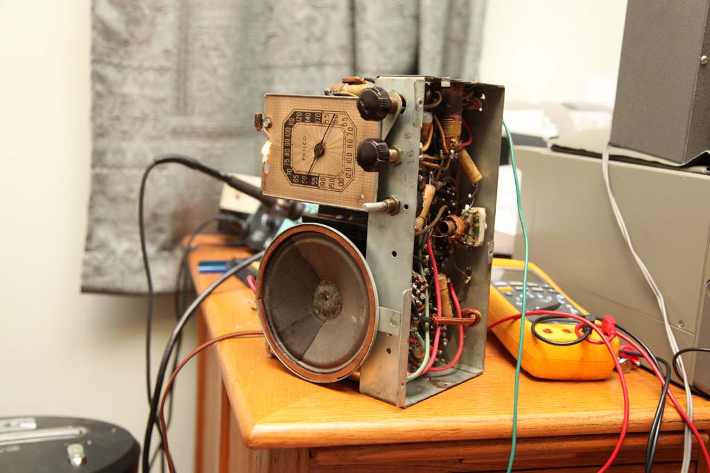
The speaker's cone patched and the speaker installed.
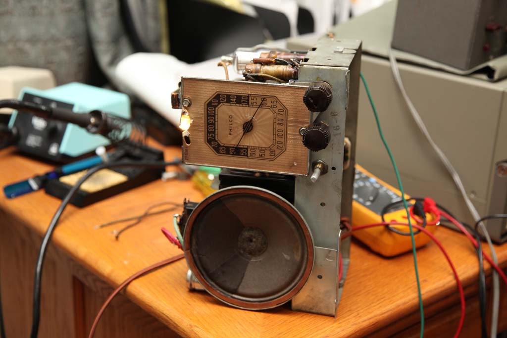
Same.
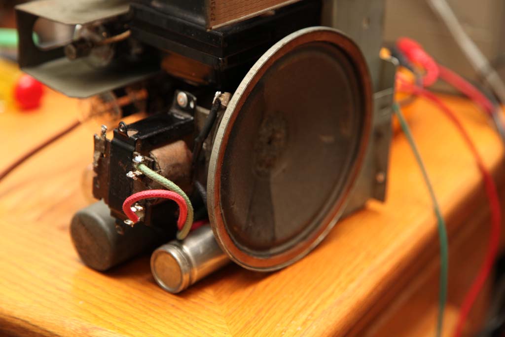
Transformer view.
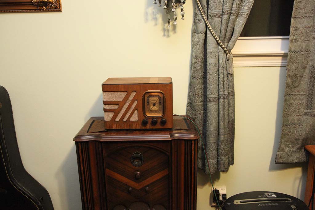
Assembled
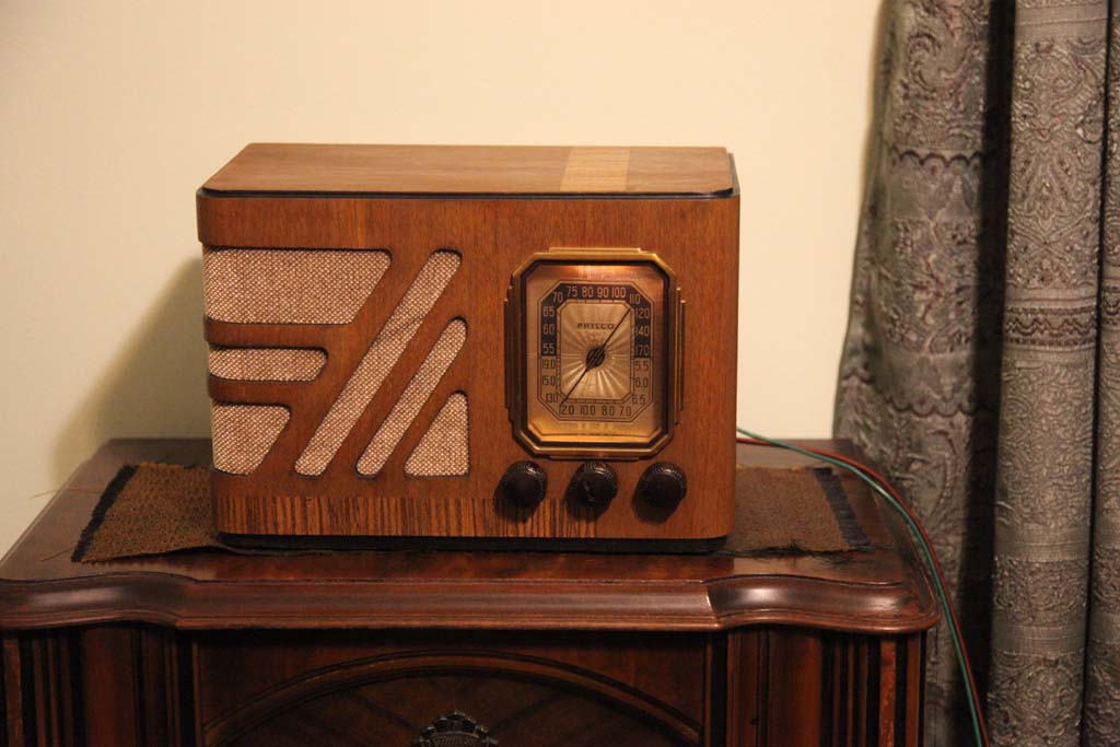
Same.
Posts: 16,495
Threads: 573
Joined: Oct 2011
City: Jackson
State, Province, Country: NJ
Now there is one last problem: there's 60HZ (I think) buzz that is pronounced when no station is coming in.
It is there even when the volume is at the minimum.
I thought it would become a bit better if I no longer use the isolation transformer and use the outlet direct. I was right, it is a bit better but still present and noticeable. Reversing the plug helps .. not.
the schematic contains the filter cap, from each line to the chassis. I observed that and used the same 0.01uF having replaced them with Y-capacitors.
I will look at it a bit more. Want to see if the Grounding the chassis helps.
Oh, the Foreign broadcast works fairly well now. A good pentagrid did it!
Users browsing this thread:
|
|
Recent Posts
|
|
Road Trip for a Philco 46-480
|
| Good morning, folks! I’ve finished the cabinet and the electrical restoration, and have detailed those in their respecti...jrblasde — 10:56 AM |
|
Studebaker/Philco AC-2687 car radio
|
| Arran,
Thanks for checking you manuals.
I appreciate that. Let me know what you find.
PhilPdouglaski — 08:46 AM |
|
Studebaker/Philco AC-2687 car radio
|
| I have some car radio service manuals, Riders I think (not to be confused with the big blue binders), so I may see if on...Arran — 01:20 AM |
|
Philco model 40-100
|
| Greetings;
Here is an update, I found a listing on fleabay for a similar chassis to yours, and it has a photo of what...Arran — 12:58 AM |
|
Philco model 40-100
|
| Greetings;
I think I may have found a clue as to what is missing, from a search I made, there is a rear view of the c...Arran — 12:12 AM |
|
Philco model 40-100
|
| I recently acquired a Philco model 40-100 farm (battery) radio. The radio was in very good condition except the red on f...mhamby — 05:59 PM |
|
Studebaker/Philco AC-2687 car radio
|
| Hello, Richard
the radio is an AC-2687 Studebaker model. The Philco model is S -5323 and the chassis p/n is S-5523Pdouglaski — 11:52 AM |
|
48-482 rear panel help
|
| The 48-482 is an AC only set as well, featuring a power transformer. While the transformer shouldn’t get “hot”, it is ye...jrblasde — 11:12 AM |
|
Studebaker/Philco AC-2687 car radio
|
| I gave a Chrysler/MoPar car radio from 1954, it was made by Philco, and it uses two chassis, one has the power supply an...Arran — 11:06 AM |
|
48-482 rear panel help
|
| Hello keithchip. You could make a hardboard back for the set, but make sure you provide plenty of ventilation holes in ...GarySP — 11:04 AM |
|
Who's Online
|
There are currently 2362 online users. [Complete List]
» 2 Member(s) | 2360 Guest(s)
|
|
|

|
 
|


![[-] [-]](https://philcoradio.com/phorum/images/bootbb/collapse.png)


