08-06-2016, 07:41 PM
Hopefully Ron, Chuck or someone who recently restored a 16B could answer this:
As I stated before, there are some discrepancies between what I have in my chassis and the 16B sch in the Rider.
Mine might be a 16B code 121 as it uses an 80 rect tube.
http://www.nostalgiaair.org/pagesbymodel...013139.pdf
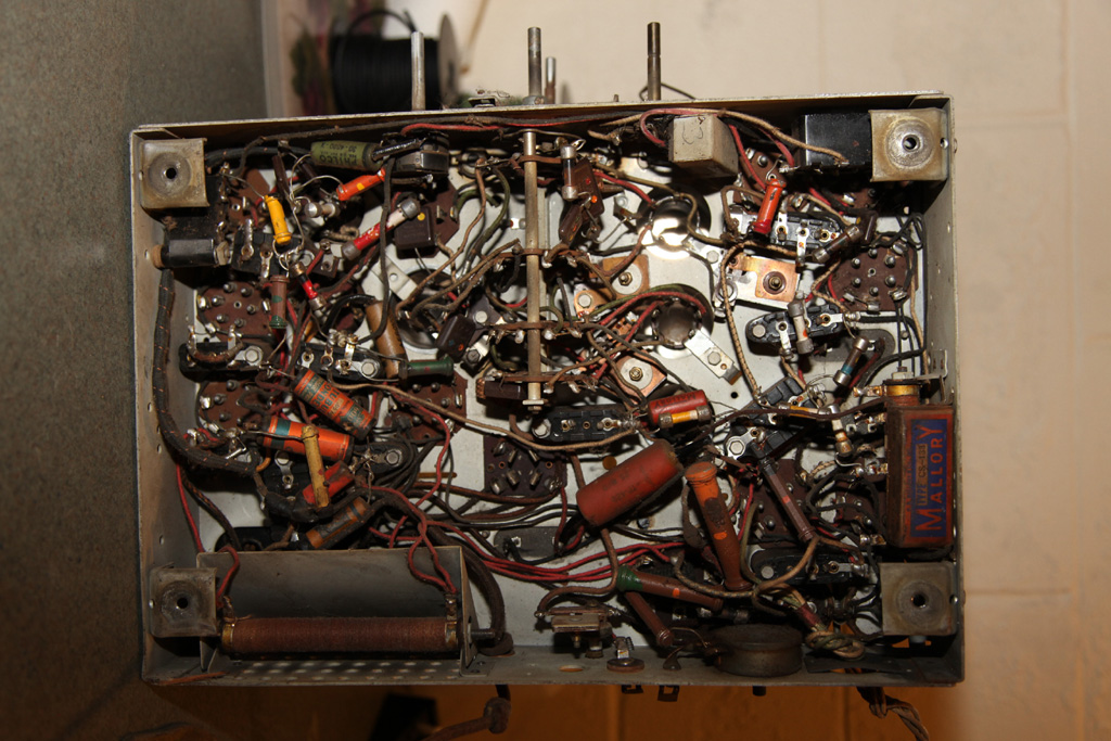
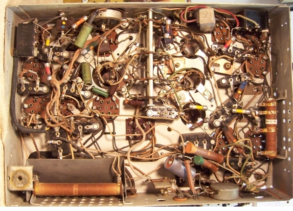
These are the pictures of my radio and someone else's (Mcclellan's website, a restoration of a 16B)
Mine

The other

Now the volume pot arrangement is different. It does look like someone touched it, but:
1) The cap (in the picture the green tubular one going to the vol pot) is a Philco cap, plus present in both radios.
2) The red (or is it orange) resistor with a yellow dot is also present in both but is absent on the sch.
3) The arrangement is different: in the chassis' the cap is connected to the top point of the resistor separating it from #53 resistor and others. In the sch the cap is connected to the output.
4. My resistor is not tapped. Dunno about the other guy's one.
There are some other things rearranged or different.
Was there a change and is there a document to reflect this? Is there a schematic that reflect the changes if those were official?
Mike.
PS. Found another image on the ARF, same deal.
http://www.antiqueradios.com/forums/view...5&t=206781
As I stated before, there are some discrepancies between what I have in my chassis and the 16B sch in the Rider.
Mine might be a 16B code 121 as it uses an 80 rect tube.
http://www.nostalgiaair.org/pagesbymodel...013139.pdf
These are the pictures of my radio and someone else's (Mcclellan's website, a restoration of a 16B)
Mine
The other
Now the volume pot arrangement is different. It does look like someone touched it, but:
1) The cap (in the picture the green tubular one going to the vol pot) is a Philco cap, plus present in both radios.
2) The red (or is it orange) resistor with a yellow dot is also present in both but is absent on the sch.
3) The arrangement is different: in the chassis' the cap is connected to the top point of the resistor separating it from #53 resistor and others. In the sch the cap is connected to the output.
4. My resistor is not tapped. Dunno about the other guy's one.
There are some other things rearranged or different.
Was there a change and is there a document to reflect this? Is there a schematic that reflect the changes if those were official?
Mike.
PS. Found another image on the ARF, same deal.
http://www.antiqueradios.com/forums/view...5&t=206781
People who do not drink, do not smoke, do not eat red meat will one day feel really stupid lying there and dying from nothing.


![[-] [-]](https://philcoradio.com/phorum/images/bootbb/collapse.png)


