08-22-2017, 12:37 PM
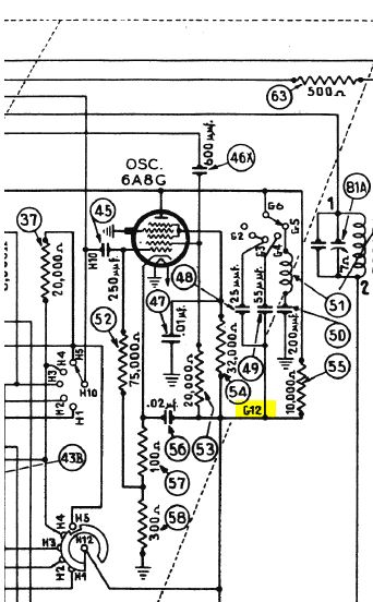
Okay I have taken the RF chassis out again and am checking all my connections to the 6A8 and all the rest of the tubes and switch wafers in the RF subchassis. Good news is that I was able to find a 37-117 code 122 on craigslist and picked it up this weekend. I will VERY carefully take a look at that RF subchassis which is untouched and looking at the schematic nearly identical to my 38-116 code 121 (as least in the RF subchassis portion). I did find a little something that looked odd on ths schematic that I did not see addressed into 1938 model changes. On the schematic between part 146 switch wafer G it shows a connection from G6 to G12 - the schematic for the 37-116 code 122 shows the same connection going to H6 and that is how it is wired on the 37-116 and 38-116 i am working on. Is that am error on the schematic - should it be H6 or G12? Here is the portion of the schematic I am referencing (the G12 I am questioning is highlighted in yellow):

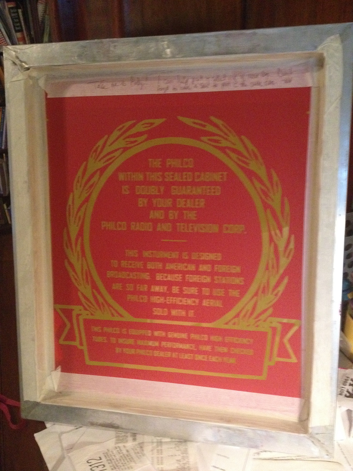
Also on another thread (http://philcoradio.com/phorum/showthread.php?tid=16254) I mentioned where I was working on making a new back for this radio. I had a friend in the printing business make me a silk screen of the Philco wording that was on the back from an logo I touched up. Now I just need to cut out the back from fiber board and silk screen it on - and I'll probably do some t-shirts while I am at it!
Also on another thread (http://philcoradio.com/phorum/showthread.php?tid=16254) I mentioned where I was working on making a new back for this radio. I had a friend in the printing business make me a silk screen
Andy Sorrell
Palmyra, Virginia


![[-] [-]](https://philcoradio.com/phorum/images/bootbb/collapse.png)


