08-29-2020, 11:23 AM
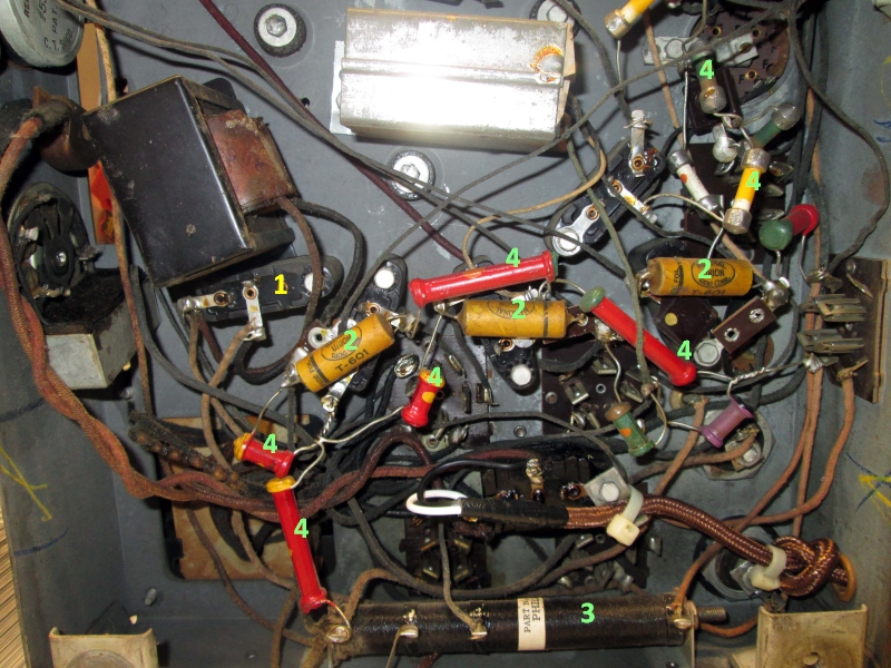
Scott, Mike is correct, those capacitors in the cans are (older) replacement electrolytic capacitors and should be replaced at some point if you plan to play the radio very often, but it would be nice if we could get the radio working again before you start replacing a lot of parts. Below I have labeled some of the parts underneath the chassis and will explain what those components are:

Your radio looks like it is an older restoration, but most of the capacitors they used are due for replacement. I have some of those that are NOS and even unused they measure a high level of leakage.
1: These are Bakelite blocks that contain paper capacitors, I have only labeled one, but you can see there are many.
2: These are (older) replacement paper capacitors that that were used to replace the capacitors in the Bakelite blocks. Instead of putting them inside the blocks they just soldered them on top of the blocks. I can't tell from the pictures, but the problem with doing that is if you don't disconnect the old blocks that old capacitance will effect the new capacitors. At any rate, at some point in time, all the capacitors in the blocks and those jumpered on top will need to be replaced.
3. This is a large wire wound resistor with several taps on it (part# 58 on the schematic). Yours looks to be in nice shape but an open in one of the sections could kill the radio.
4. These are resistors, we call them dog bone resistors today. I didn't label them all but enough so you should be able to ID the rest. These typically creep higher in value and if 10 or 20% higher than marked should eventually be replaced.
The easiest fix is a bad tube or maybe one that isn't seated well in its socket. Pulling them out one at a time, cleaning the pins with scotchbrite and reseating is not a bad idea. Have you tried putting the old #24 back in the radio yet? If you have access to a tube tester it would be a good idea to test them.
EDIT: If you need schematics and part lists PM me your email address and I'll send you some hi-res copies.
Edit2: Rather than regurgitate what has already been covered here are some links you might find helpful:
The first is a restoration of a model 90:
https://mcclellans.com/Philco90Restoration.htm
Another restoration thread by Steve Davis. Although this is a push-pull 47 chassis you'll find many similarities:
https://philcoradio.com/phorum/showthread.php?tid=20685
From the Philco library this tells you what is inside each of those Bakelite blocks:
https://web.archive.org/web/201702271004...lokcap.htm
And here Mike (morzh) describes the no-mess method of re-stuffing those Bakelite blocks with fresh capacitors:
https://philcoradio.com/library/index.ph...soldering/
John KK4ZLF
Lexington, KY
"illegitimis non carborundum"


![[-] [-]](https://philcoradio.com/phorum/images/bootbb/collapse.png)


