06-06-2024, 08:56 PM
This is an important follow up....
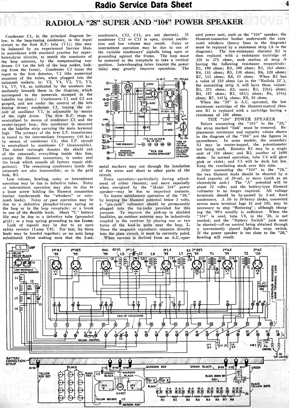
It appears the volume control for DC operation only controls the first IF, there is some convoluted routing for the filament connections to do that. So indicated, the resistance cannot be some 200 some odd ohms but must be around 30 ohms.
I cannot find any other clear notation of the original value...
To save hinting for reference schematic here is the Gernsback for DC with jumper strip, note AC resistance strip is off to the lower right as a group of resistors, unconnected:

 PDFsam_AC operation of Radiola 25 & 28RCA-Victor-Service-Notes-1923-1928.pdf Size: 778.88 KB Downloads: 133
One has to wade through the conversions for the Radiola 25 (ignore) to get to the Radiola 28 info.
Reverse engineer the change over for AC. Note the mention of a connection. In particular, page 14 which describes a re-positioning of Whisker 16 to terminal 19 from terminal 17. You will move it to terminal back to terminal 17...
You will also have to consider what isn't there because the AC mods were for the Receptrad power supply...
I will scavenge through the parts I have. I have a lot of chassis parts for Radiola 25 (DC) I believe I have the low resistance cartridge and relatively sure I have the caps. Please allow several days for me to get this done as I have other Summer (household) projects going...
In mean time be ABSOLUTELY SURE that the filament circuits have no accidental connections to the B+ via the new jumper strip and by the battery harness. Do not remove any wires on the terminals at this time as they maybe the extension leads to the bypass caps. Once those caps are in hand the wires if not needed can go away.
What is the spacing of the two filament test jacks and are they horizontally placed?
I may have a meter...
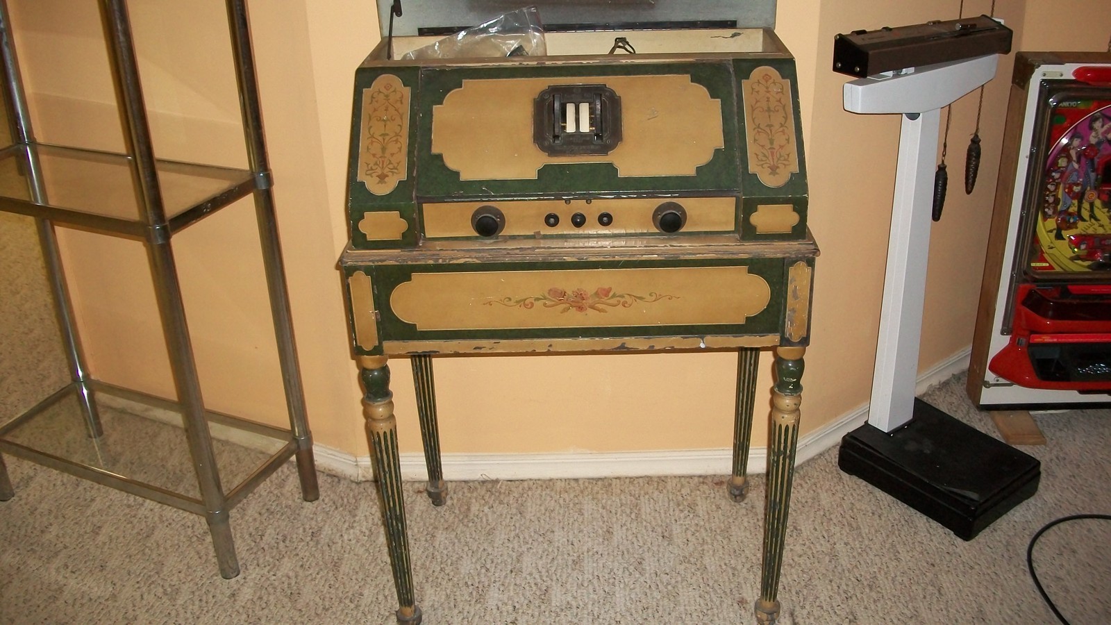
Take a look at this uniquely finished 28 done back in the 20's. Download the image so it can be blown up to see the detail...

Best!
Chas
It appears the volume control for DC operation only controls the first IF, there is some convoluted routing for the filament connections to do that. So indicated, the resistance cannot be some 200 some odd ohms but must be around 30 ohms.
I cannot find any other clear notation of the original value...
To save hinting for reference schematic here is the Gernsback for DC with jumper strip, note AC resistance strip is off to the lower right as a group of resistors, unconnected:
 PDFsam_AC operation of Radiola 25 & 28RCA-Victor-Service-Notes-1923-1928.pdf Size: 778.88 KB Downloads: 133
One has to wade through the conversions for the Radiola 25 (ignore) to get to the Radiola 28 info.
Reverse engineer the change over for AC. Note the mention of a connection. In particular, page 14 which describes a re-positioning of Whisker 16 to terminal 19 from terminal 17. You will move it to terminal back to terminal 17...
You will also have to consider what isn't there because the AC mods were for the Receptrad power supply...
I will scavenge through the parts I have. I have a lot of chassis parts for Radiola 25 (DC) I believe I have the low resistance cartridge and relatively sure I have the caps. Please allow several days for me to get this done as I have other Summer (household) projects going...
In mean time be ABSOLUTELY SURE that the filament circuits have no accidental connections to the B+ via the new jumper strip and by the battery harness. Do not remove any wires on the terminals at this time as they maybe the extension leads to the bypass caps. Once those caps are in hand the wires if not needed can go away.
What is the spacing of the two filament test jacks and are they horizontally placed?
I may have a meter...
Take a look at this uniquely finished 28 done back in the 20's. Download the image so it can be blown up to see the detail...
Best!
Chas
Pliny the younger
“nihil novum nihil varium nihil quod non semel spectasse sufficiat”


![[-] [-]](https://philcoradio.com/phorum/images/bootbb/collapse.png)


