01-12-2025, 10:54 PM
Hi Roger,
First off, Welcome to the Philco Phorum! Secondly, apologies in advance for the length of this post.
I am sure that Gary will answer you the next time he is on line. On the bottom right of the page, you will see the Avatars(?) of those members who are currently on line.
The following link is from the Philco Library on this Phorum and shows the version with the 7J7 Pentagrid Convertor. Triode-Heptode First Detector. (Edited 01/14/2025 for Correction to description of the 7J7) I must apologize that in this post, I described the 7J7 as a pentagrid convertor based on my interpretation of the schematic in the Philco library. After consulting the RCA Receiving Tube Manual, I note that the 7J7 is a triode-heptode (a heptode being a tube with a cathode, plate and 5 grids) tube, similar in function to the 6J8 other than the base design and pinouts. The 6K8, a triode-hexode (a hexode being a tube with a cathode, plate and 4 grids) while different in design does the same function. The difference between the triode-hexode or triode-heptode and the Pentagrid or autodyne detectors is that the triode-heptode or triode-hexode provides a "separate electron path" (sharing only the cathode) for the oscillator and mixer with the advantages of having both "tubes" in the same envelope. The Pentagrid Convertor (Heptode) uses a "grid - plate" as the oscillator plate, but the "electron paths" of the oscillator and mixer are the same, passing through all grids.
Part48-Philco 1940 RMS Year Book.pdf
Now this is where it gets interesting!
The same document states that there are certain runs with a 6J8 Octal tube replacing the 7J7. Per the Radiomuseum website, The 6J8 is supposedly a Russian version of a 6K7 remote cutoff pentode, hardly the tube one would want to use as a convertor. However, Radiomuseum also lists a 6J8 Triode Heptode, where the triode is used as an oscillator and the heptode section is used as a mixer. This triode oscillator / heptode mixer configuration usually works better at high frequencies than the typical pentagrid convertor. Remember, that in the late 1930s to 1960s or later, shortwave was to many people what the internet is today. Shortwave was the window to news (true or propaganda) of the developing conflicts that culminated in WWII, and for many immigrants, news of the land that they left. (Edited 01/14/2025- The fact that the 7J7 and 6J8 are both triode-heptodes with similar construction and function other than basing, and the fact that Philco does not give tube pinouts on the schematic may be the reason why a separate schematic for sets using the 6J8 was not published.
The next issue is that your radio has a 6K8, which is a triode hexode, not a triode heptode. These are not the same tube. Is the tube location sticker still in your radio? Does it state 7J7, 6J8 or 6K8?
To further complicate things, there is no insert in the Philco Service Document for your radio showing the 6J8 circuit.
The following may help:
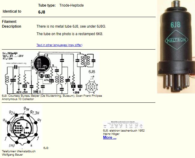
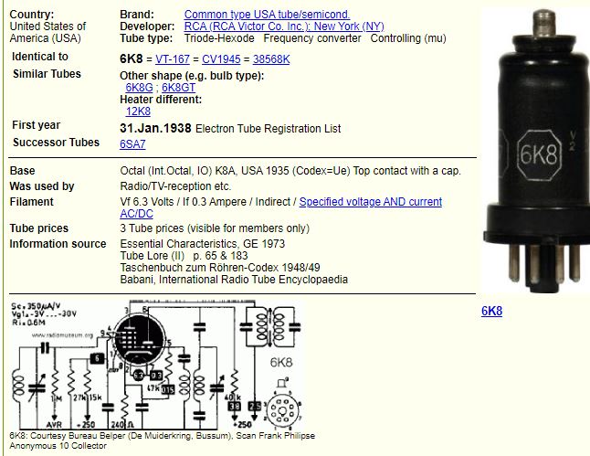
Attached below are 2 pages from Radiomuseum describing the 6J8 and the 6K8 and showing typical oscillator mixer circuits with tube "pinouts":


Attached below is a link to the Philco 41-722 which uses the 6J8 Triode Hexode:
Part67-Philco 1941 RMS Year Book.pdf
Attached is an "Emergency Tube Substitution Guide published by RCA during WWII. (New radio and replacement part production stopped in 1942 to build the electronics that were required by the US Military.) The manual does not show that a 6K8 can replace a 6J8. Both tubes are listed.
Now, for the poor sound issue:
Are you dealing with a distortion issue? The fact that you have a 6K8 instead of a 6J8 may be an issue.
I am a believer in "divide and conquer troubleshooting. In addition, I like to add "aux inputs" to my radios so that I can pipe music from an MP3, computer, etc., a great way to get "old time" radio to play from your "old time radio" (pardon the pun). It also helps in the diagnosis of where the distortion comes from. The amplifier section of this radio should sound rather clean. Not Fisher, Scott or Marantz clean, but clean. The best place to "inject" an outside signal is at the junction of the detector and the Volume control. If you are interested, I will do a diagram. Any modern speaker is likely better than the original. However, there are 2 issues that must be dealt with:
Do recap the radio and check all resistors. For this and other radios, Philco has a rather novel method of getting the inverted signal for the second Pentode in the Push Pull Circuit. Note that there is no Phase Invertor Stage. Note the 3900 Ohm resistor between B+ and the screen of one of the 41s. Note the capacitor between the screen of that 41 and the grid of the other 41. That is how the inverse phase needed for the second pentode in the push pull output is generated. It is critical that all caps and resistors in this section of the circuit be exact (within stated tolerances) and in good shape.
Again, sorry for the length of this. Hope it helps!
First off, Welcome to the Philco Phorum! Secondly, apologies in advance for the length of this post.
I am sure that Gary will answer you the next time he is on line. On the bottom right of the page, you will see the Avatars(?) of those members who are currently on line.
The following link is from the Philco Library on this Phorum and shows the version with the 7J7 Pentagrid Convertor. Triode-Heptode First Detector. (Edited 01/14/2025 for Correction to description of the 7J7) I must apologize that in this post, I described the 7J7 as a pentagrid convertor based on my interpretation of the schematic in the Philco library. After consulting the RCA Receiving Tube Manual, I note that the 7J7 is a triode-heptode (a heptode being a tube with a cathode, plate and 5 grids) tube, similar in function to the 6J8 other than the base design and pinouts. The 6K8, a triode-hexode (a hexode being a tube with a cathode, plate and 4 grids) while different in design does the same function. The difference between the triode-hexode or triode-heptode and the Pentagrid or autodyne detectors is that the triode-heptode or triode-hexode provides a "separate electron path" (sharing only the cathode) for the oscillator and mixer with the advantages of having both "tubes" in the same envelope. The Pentagrid Convertor (Heptode) uses a "grid - plate" as the oscillator plate, but the "electron paths" of the oscillator and mixer are the same, passing through all grids.
Part48-Philco 1940 RMS Year Book.pdf
Now this is where it gets interesting!
The same document states that there are certain runs with a 6J8 Octal tube replacing the 7J7. Per the Radiomuseum website, The 6J8 is supposedly a Russian version of a 6K7 remote cutoff pentode, hardly the tube one would want to use as a convertor. However, Radiomuseum also lists a 6J8 Triode Heptode, where the triode is used as an oscillator and the heptode section is used as a mixer. This triode oscillator / heptode mixer configuration usually works better at high frequencies than the typical pentagrid convertor. Remember, that in the late 1930s to 1960s or later, shortwave was to many people what the internet is today. Shortwave was the window to news (true or propaganda) of the developing conflicts that culminated in WWII, and for many immigrants, news of the land that they left. (Edited 01/14/2025- The fact that the 7J7 and 6J8 are both triode-heptodes with similar construction and function other than basing, and the fact that Philco does not give tube pinouts on the schematic may be the reason why a separate schematic for sets using the 6J8 was not published.
The next issue is that your radio has a 6K8, which is a triode hexode, not a triode heptode. These are not the same tube. Is the tube location sticker still in your radio? Does it state 7J7, 6J8 or 6K8?
To further complicate things, there is no insert in the Philco Service Document for your radio showing the 6J8 circuit.
The following may help:
Attached below are 2 pages from Radiomuseum describing the 6J8 and the 6K8 and showing typical oscillator mixer circuits with tube "pinouts":
Attached below is a link to the Philco 41-722 which uses the 6J8 Triode Hexode:
Part67-Philco 1941 RMS Year Book.pdf
Attached is an "Emergency Tube Substitution Guide published by RCA during WWII. (New radio and replacement part production stopped in 1942 to build the electronics that were required by the US Military.) The manual does not show that a 6K8 can replace a 6J8. Both tubes are listed.
Now, for the poor sound issue:
Are you dealing with a distortion issue? The fact that you have a 6K8 instead of a 6J8 may be an issue.
I am a believer in "divide and conquer troubleshooting. In addition, I like to add "aux inputs" to my radios so that I can pipe music from an MP3, computer, etc., a great way to get "old time" radio to play from your "old time radio" (pardon the pun). It also helps in the diagnosis of where the distortion comes from. The amplifier section of this radio should sound rather clean. Not Fisher, Scott or Marantz clean, but clean. The best place to "inject" an outside signal is at the junction of the detector and the Volume control. If you are interested, I will do a diagram. Any modern speaker is likely better than the original. However, there are 2 issues that must be dealt with:
- Correct voice col impedance for the transformer in use
- Correct resistor or choke in place of the field coil (and likely the necessity tto increase the capacity of the filter caps).
Do recap the radio and check all resistors. For this and other radios, Philco has a rather novel method of getting the inverted signal for the second Pentode in the Push Pull Circuit. Note that there is no Phase Invertor Stage. Note the 3900 Ohm resistor between B+ and the screen of one of the 41s. Note the capacitor between the screen of that 41 and the grid of the other 41. That is how the inverse phase needed for the second pentode in the push pull output is generated. It is critical that all caps and resistors in this section of the circuit be exact (within stated tolerances) and in good shape.
Again, sorry for the length of this. Hope it helps!
"Do Justly, love Mercy and walk humbly with your God"- Micah 6:8
"Let us begin to do good"- St. Francis
Best Regards,
MrFixr55


![[-] [-]](https://philcoradio.com/phorum/images/bootbb/collapse.png)


