Beginning a 37-620 Restoration
Posts: 172
Threads: 10
Joined: Mar 2026
City: Franklin
State, Province, Country: Maine
Mike,
I've added a sketch here of the current configuration where power enters the chassis. Sorry if this seems like basic stuff, but I want to make sure I've got 100% understanding of the particular issues before I start swapping stuff around.
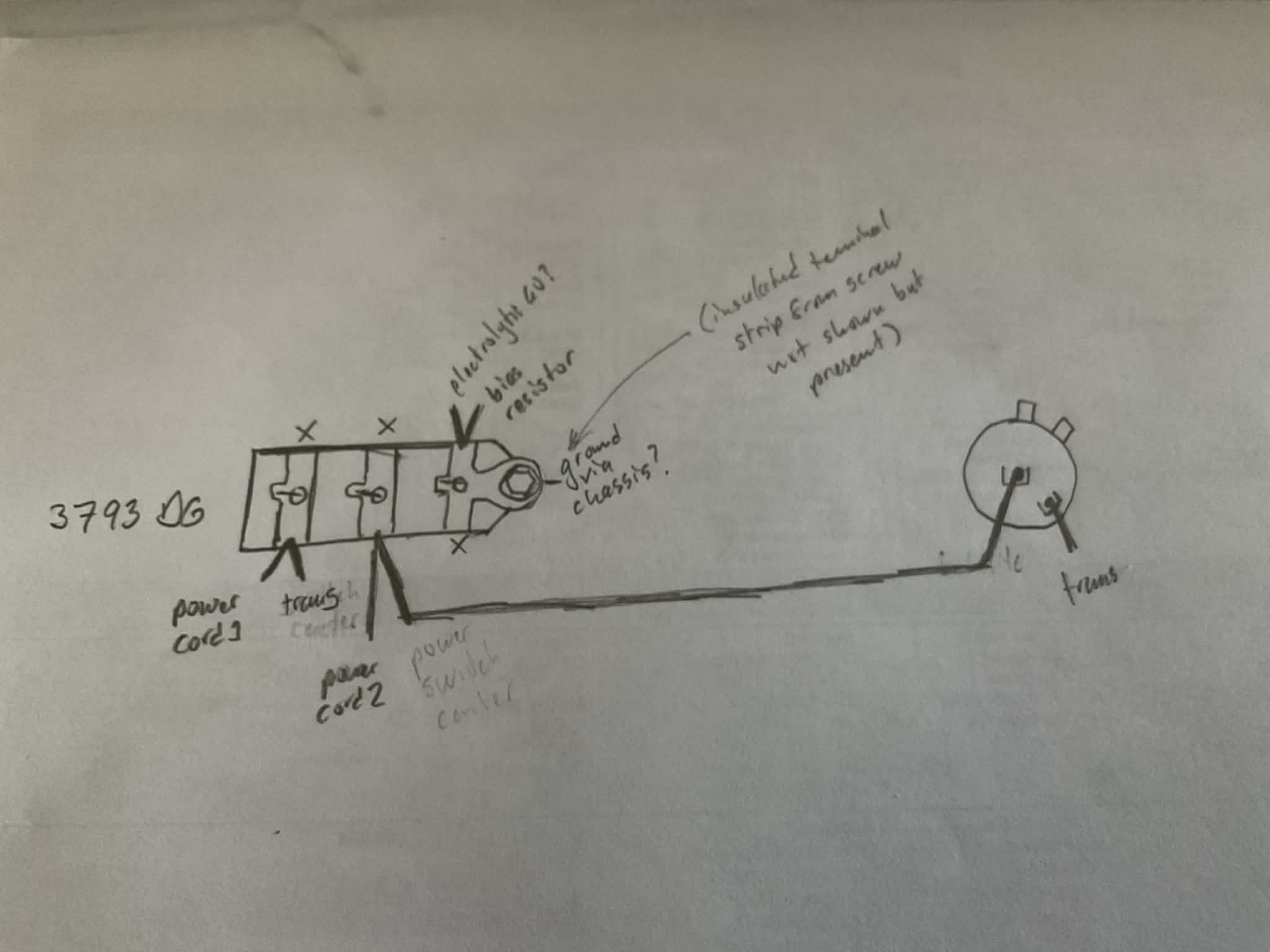
Current power cord (non-polarized) enters chassis, one lead connecting to left-most lug, second lead connecting to center lug.
The left-most lug also has a white wire which goes to the transformer - I suspect this is what on the schematics is marked as WHITE 1.
The center lug has a wire that runs to the center lug on the power/tone control pot
The right-most lug connects to one of the replaced (not by me) electrolytics (I believe number 60) and the bias resistor, and, I suspect, ground via the screw to the chassis.
There is a terminal strip (not illustrated) which branches off of the screw which appears to be insulated and electrically separate for other components to solder to.
On the power/tone control pot, the only other obviously connected lug is the one on the back, adjacent to the center, which is a white wire, also to the transformer (presumably WHITE 2 on the schematic). The other two visible lugs are empty. There may be another lug next to the two empty ones but it's hard to see if it really is a part of the pot, but if it is, it is in contact with the chassis above it - maybe ground for the tone control side?
To move the cap to the right, as you said, are you suggesting to wire it so that the switch is directly connected to one of the leads coming from the power cord, and the output to the place where that lead had originally connected to the capacitor? Does it matter which one? Then, where the capacitor used to run to the switch would go to the transformer directly, yes?
Since I plan to put on a polarized plug end, the prong that is hot (narrow) should be going to the switched side ideally, yes?
As for fuse(s), it's preferable to put them as close to the power cord as possible, before the switch, yes? What rating is best to use for this application?
And lastly, does it seem like the tone control aspect is disconnected if there are only two wires presently connected to the power/tone control pot? Without knowing the purposes to the various lugs on the pot I'm at a loss as to what might be missing. I've looked, but I can't even find pictures of the 42-1182, let alone any reference material. They seem to be scarce and I believe this one is original.
Posts: 172
Threads: 10
Joined: Mar 2026
City: Franklin
State, Province, Country: Maine
Dale,
Thanks for the advice. I'll make it a point to test the resistors that I remove. It will be interesting to see the difference between tests.
I am what I would call a novice at soldering. I have done it a handful of times before (replacing capacitors in a couple modern Samsung TVs, other small projects). I definitely don't have the vacuum/pump setup for desoldering. I do have the braid to sop it up. This is already my biggest soldering project to date.
Thanks again,
Roy
Posts: 18,427
Threads: 622
Joined: Oct 2011
City: Jackson
State, Province, Country: NJ
Glyphmon
A suggestion: this is a very much non-essential stuff.
Save these questions you have about mods (not about restoration) in a separate folder and get the radio working and aligned first.
Then, if so desired, we can talk mods.
Otherwise you get yourself distracted.
Try to concentrate on restoration for now.
People who do not drink, do not smoke, do not eat red meat will one day feel really stupid lying there and dying from nothing.
Posts: 1,797
Threads: 55
Joined: Feb 2015
City: Roseville, MN
OK, let's look at question 3. The schematic shows the ton switch and tone caps all close to the 6F6 power output tube. When you see the chassis you see the switch is an augment of the power switch. And indeed the schematic shows this (#59) with the broken line between the tone switch and the power switch. When the knob of the power switch is turned the tone switch turns; they are two separate switches moving at the same time. The caps for the tone circuit (#56 & #57) are close by the output tube. On mine one is near the tube and the other is on the other side of the chassis. The wiring goes from tube to switch the longer way around because if it went directly between switch and tube it would cross the danger zone (power transformer and HT power supply). Hum is not good for audio circuits. Looking at the pictorial for your set, cap 56 is attached to the ground terminal of the bakelite block and that corresponds with the schematic. You said there is a blue wire attached to that lug so it will be difficult to determine where it goes. You should verify it is ground because in my set the bakelite block doesn't have that terminal grounded. Either there's an ungrounded part somewhere or someone was using the wire to ground out test points.
I'll go look at question 4 now.
Posts: 1,797
Threads: 55
Joined: Feb 2015
City: Roseville, MN
Reply to question 4: This is called a terminal strip with terminal lugs for soldering parts and wires.This blue wire is also a part of the tone switch circuit. If you look at the schematic where 46, 47 and blue wire meet then follow part 46 (51k resistor) to a tap on the volume control. This is a tone compensation circuit for low volume settings. When the tone switch is in the ON position it puts a ground on the blue wire shorting out cap 47. Someone added a ground wire spliced in to the blue wire to permanently short out the effect of cap 47. I suspect that after you replace the paper caps and remove the spliced wire you will hear a noted difference in the tone switch settings.
BTW Try to avoid using Philco part numbers when referring to the schematic or parts layout if you can. It's easier and quicker for us to identify them if you use the reference number or value. Many of the part numbers were obsolete by the time the radio left the assembly line.
(This post was last modified: 03-29-2026, 04:25 PM by RodB.)
Posts: 172
Threads: 10
Joined: Mar 2026
City: Franklin
State, Province, Country: Maine
Rod,
Thanks for the information. You confirmed what I was beginning to think by looking at the schematic, that the tone control and volume switch, while part of the same assembly are electrically two separate components.
I may not have explained correctly - the blue wire in question runs from the terminal strip, around the front of the chassis and then, near the power/tone control, is spliced and taped, becoming a short section of white wire which then goes to a bolt on the chassis which is one of the four mounting bolts for the power transformer.
Would there be any harm in trying to put the tone control back to the way it should have been from the factory? Am I correct in thinking that the blue wire from the terminal strip as described above, and the disconnected wire coming off of what on the schematic is Cap 57 but in this Run 2 set is the 8318-SU bakelite, were both supposed to connect to lugs on the tone control? Which lugs would go to which?
Just placed an order for capacitors and resistors a few minutes ago so in a few days I hope to begin actually swapping out parts.
Best wishes,
Roy
Posts: 5,652
Threads: 56
Joined: Sep 2008
City: Sandwick, BC, CA
Your diagram mostly makes sense, on Philco sets they used Bakelite blocks as terminal strips for the power cord, and power switch, and power transformer primary winding right into the late 1940s. Typically that block would also house the two capacitors connected between either leg of the power line, and the chassis. The caps inside that block will need to be replaced too, but with modern safety rated capacitors that fail open circuit rather then short circuit. You do not need them in there to get the set going, they are there to eliminate interference from the power line from getting into the radio's power supply.
Regards
Arran
Posts: 5,652
Threads: 56
Joined: Sep 2008
City: Sandwick, BC, CA
Also regarding the resistors, as Mike says, you can change them all if you like but if all but two are within a tolerance of + or - 20% I wouldn't bother. I've had sets were they were so far off that I had to change 8 out of 10 or worse, the dogbone style resistors are often like that, as are one variety popular in many post war sets, they had a molded body with a rough finish, total junk!
Regards
Arran
Posts: 172
Threads: 10
Joined: Mar 2026
City: Franklin
State, Province, Country: Maine
Arran,
Thanks for the tips. Dale had pointed out that since my testing was done in-circuit that the readings could have been artificially low. As I said to Mike, I don't have a tremendous desire to do extra work in the first place, but at this point I've ordered to basically replace everything - I'm in here and don't want to have to pull stuff apart again because something still needs doing. I'll test what comes out to see how different the results are, for informational purposes more than anything.
Y2 safety caps for the bakelite at the power cord are part of that order, per another response. Hoping to have a much better performing unit when all is said and done. New cord, wire, an inline fuse holder also on order. Looking into replacement grommets for the tuning chassis and where the chassis mounts to the cabinet. Then I can move on to the cabinet work which looks like it will be complex in its own way. Peeled photo finish in a few spots is the majority of the damage to the cabinet, otherwise, it's in pretty good shape.
Best wishes,
Roy
Posts: 172
Threads: 10
Joined: Mar 2026
City: Franklin
State, Province, Country: Maine
Update, and tone control question as I near the end of re-capping.
Things are going reasonably well - I'm actually enjoying the process of replacing the capacitors and resistors so far, for the most part. As I'm nearing the end of that phase, I would like to follow up on a question I hadn't gotten an answer to yet.
In the process, I've de-soldered the shorted tone control wire and that and the tiny wire are now both disconnected and taped over. I'd like to reconnect them to the tone control, but not sure which lugs go to which on the pot. Can anyone offer guidance as to which arrangement I should do? I'd just like to avoid re-doing soldering if possible.
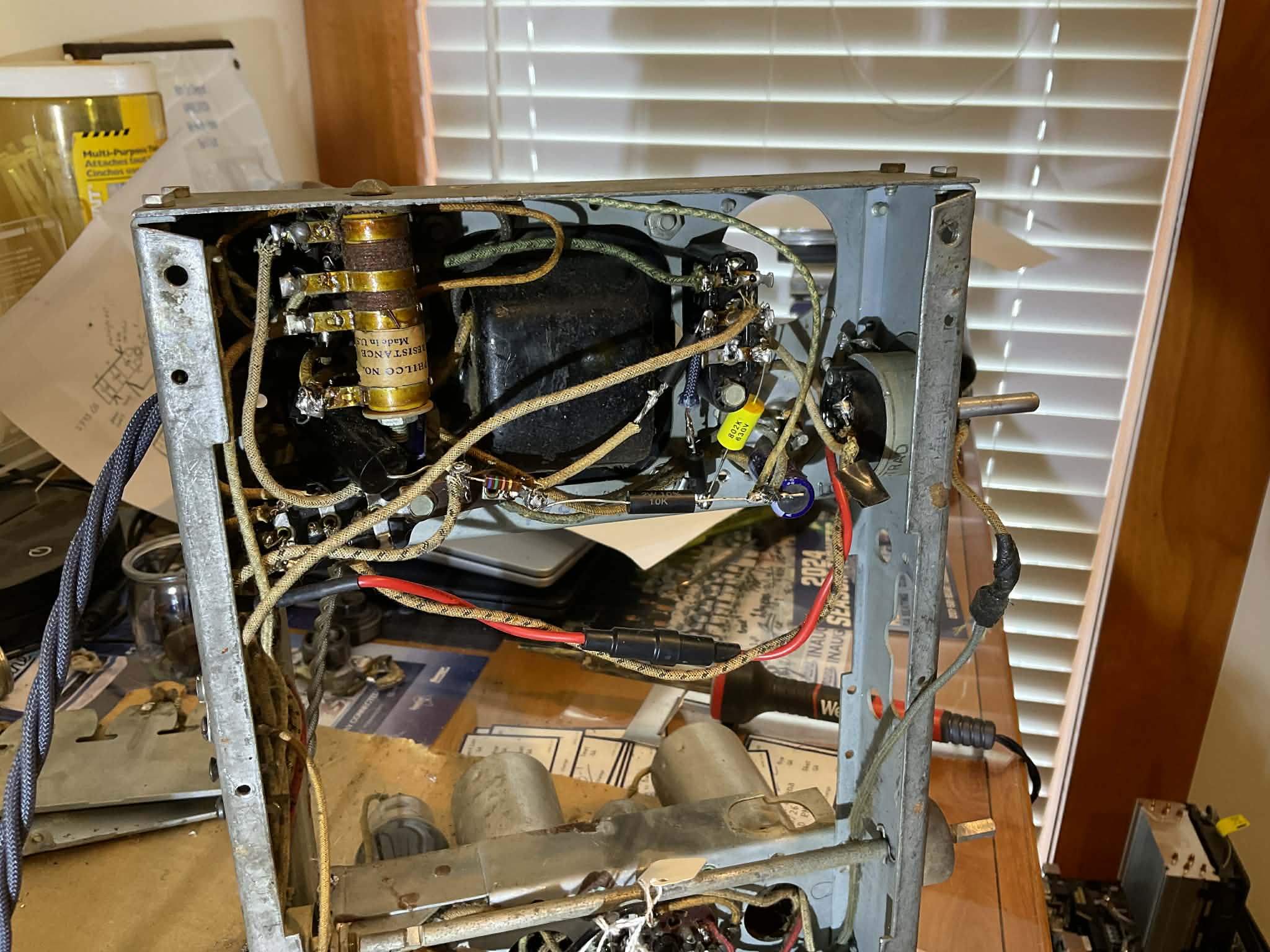
Other tasks completed in the process: added fuse which made it easier to move the switch in between the new power cord and the bakelite at the rear of the chassis. Also re-ran the wires to the speaker since those were ratty either from UV exposure or small teeth. Still have a little patching to do on the tuning sub-chassis.
Best wishes,
Roy
Posts: 1,797
Threads: 55
Joined: Feb 2015
City: Roseville, MN
I'm not sure what you mean by the tiny wire. When you discuss wire connections you should tell us what they are connected to, referring to schematic numbers.
The way I understand it, your blue wire runs from the tone switch along the front of the chassis then back to the caps attached to the long terminal strip, and it's the same as my chassis. It connects to the junction of a 0.008mfd cap (#47) and a 51k resistor (#46). When the tone switch selects the blue wire it puts a ground on the blue wire shorting out cap 47. This changes the tone characteristics in the volume control circuit. If you have replaced cap 47 then you can omit the wire that was attached to the blue wire to ground.
Posts: 172
Threads: 10
Joined: Mar 2026
City: Franklin
State, Province, Country: Maine
Rod,
Sorry, was relying on my prior explanation and photos and trying to avoid saying "short" wire.
There are at present two wires in question disconnected and taped in the photo: the short wire between tone control and where Capacitors 56 and 57 tie together; the long (originally blue, dangling in and outside the chassis at the right in the photo above) wire which on the schematic runs between tone control and the first solder point on the terminal strip (with Capacitor 47 and Resistor 46). Nothing has been connected to the tone control pot since I began working on the radio as far as I can tell.
There are two previously-soldered lugs on the tone control pot but no indication that I can see as to which might correspond to which wire.
In the previous configuration, the short wire mentioned above may have not even been connected at all, and the blue wire was soldered to a ground point on the chassis near the power transformer. I think it was your thought that someone had permanently grounded the tone control for some reason.
Best wishes,
Roy
Posts: 1,797
Threads: 55
Joined: Feb 2015
City: Roseville, MN
Got it, I think. Now, the tone control is a 4 position switch. There may be a terminal that is ground , this would be the common terminal on the schematic. If one of the previous wired terminal lugs is the in second position then that is for the blue wire. The junction of 56 and 57 goes to the end terminal opposite end from the blue wire.
(This post was last modified: 04-07-2026, 02:25 PM by RodB.)
Posts: 172
Threads: 10
Joined: Mar 2026
City: Franklin
State, Province, Country: Maine
Rod,
I probably should have tried removing the part from the chassis sooner to be able to tell, but here's a picture of the power switch/tone control. There are in fact three lugs on the tone control section, one of which (right-most in this photo) was in contact with but not attached to the chassis.
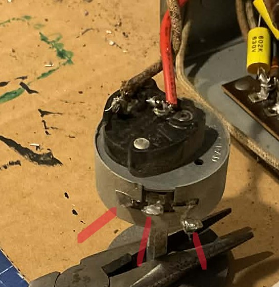
When you say four-position switch, do you mean discrete positions like the band switch with three positions? Because this does not turn in that way - yes, "off" is one position, but once in the "on" position, it is a smooth, continuous movement (once in the "on" position for power) to the end of its range of motion. Does that suggest that perhaps this is not the original part and may not actually function as a tone control anymore? I tried to find photos of the 42-1182 part but came up empty. This has Electrad 5000 ohms and RI-234 stamped on the side.
Best wishes,
Roy
(This post was last modified: 04-07-2026, 05:20 PM by glyphmon.)
Posts: 18,427
Threads: 622
Joined: Oct 2011
City: Jackson
State, Province, Country: NJ
This looks like a potentiometer to me.
People who do not drink, do not smoke, do not eat red meat will one day feel really stupid lying there and dying from nothing.
Users browsing this thread: 1 Guest(s)
|
|
Recent Posts
|
|
Philco P45-6365 Universal Transformer Instruction Manual
|
| Can anyone guide me to where this may be found?GRG — 03:00 PM |
|
54C Complete Teardown/Rebuild
|
| I don't think that I have encountered a 12Z3 before, curious how it uses one of those but includes a #43, which is a 25 ...Arran — 02:17 PM |
|
HiFi (Chifi) tube amp build - but my own design.
|
| It's the other forum. I'm also in DIY, but mostly read there. Honestly, I kinda jumped into this without much thought to...TV MAN — 10:43 AM |
|
Philco 71 Code 125
|
| Hello,
I am in need of a schematic for this radio. Mine has the three separate circular tube shields and a shadow me...dconant — 08:06 AM |
|
Stromberg Carlson 1500 Squeal
|
| And life just keeps getting more complicated.dconant — 07:57 AM |
|
54C Complete Teardown/Rebuild
|
| Hello Roy,
here is this one
sincerely Richardradiorich — 12:45 AM |
|
54C Complete Teardown/Rebuild
|
| Richard,
Had grabbed it already but thank you just the same. I find myself wanting to find some way to block out the...glyphmon — 12:03 AM |
|
54C Complete Teardown/Rebuild
|
| Hello roy,
here is a link to the schematic .
Sincerely Richardradiorich — 11:54 PM |
|
54C Complete Teardown/Rebuild
|
| Richard,
The Silvertone 2014 also is a transformerless set, so I am incorporating a 1:1 600 ohm audio isolation transfo...glyphmon — 11:37 PM |
|
Preliminary work on wife's Silvertone 2014
|
| Did an alignment today which was interesting. IF alignment went great, almost all was already spot-on. Adjusting on th...glyphmon — 11:35 PM |
|
Who's Online
|
There are currently 1787 online users. [Complete List]
» 2 Member(s) | 1785 Guest(s)
|
|
|

|
 
|







