Beginning a 37-620 Restoration
Posts: 1,797
Threads: 55
Joined: Feb 2015
City: Roseville, MN
Yes, I agree Mike. Someone replaced the switch with a tone pot. The original, like the one in my set and displayed in the schematic, is a four position switch. That explains the ground wire splice.
Some tone control circuits have a pot in series with a capacitor to vary the tone. I assume the two terminals on the control are one end and the wiper. I'm thinking the only way to use it is to connect it that way.
Posts: 18,427
Threads: 622
Joined: Oct 2011
City: Jackson
State, Province, Country: NJ
Depending on how it is used. If the resistor (pot) is connected to the cap that is connected to the tube's plate, make sure the pot is grounded and the cap is the one that is wired to the plate. Electrically it is all the same, but you do not want to take a chance of electrical breakdown in a pot and to be exposed to the plate voltage (pots are not necessarily hi-V rated).
People who do not drink, do not smoke, do not eat red meat will one day feel really stupid lying there and dying from nothing.
Posts: 1,797
Threads: 55
Joined: Feb 2015
City: Roseville, MN
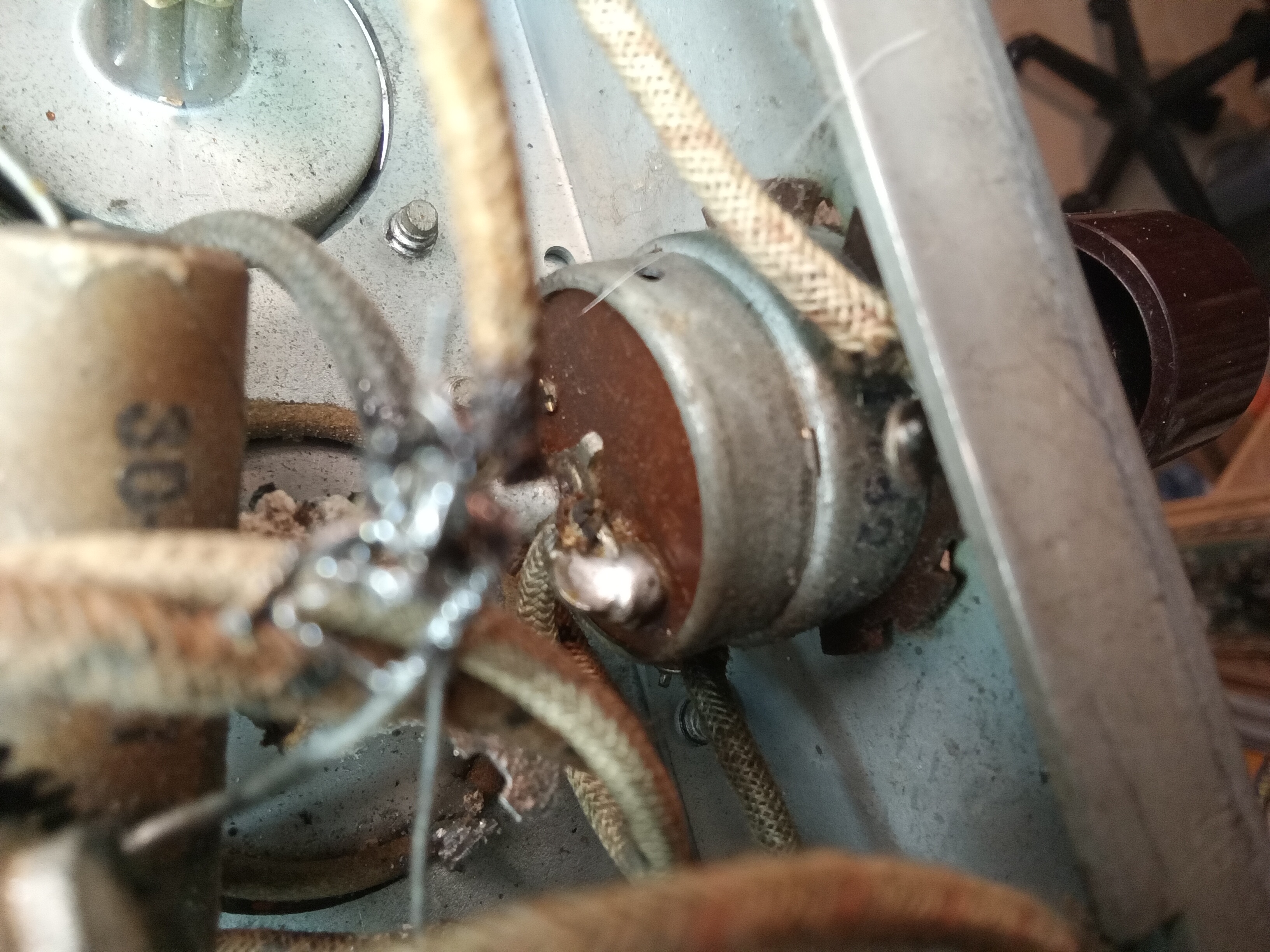
Here's a photo of mine. Not much to see when it's installed. The white wire, upper left, goes to the two caps in the tone circuit and the blue wire is in the shade under the switch and it runs back to the resistor/cap on the volume control.
Posts: 172
Threads: 10
Joined: Mar 2026
City: Franklin
State, Province, Country: Maine
So, a search on "RI-234" turns up as a 5000 ohm antenna shunt in a 1932 issue of Radio Bargain News hosted by World Radio History. Even so, I can't find anything that shows a diagram or schematic that indicates how to connect it. Right now, in my radio, it's just the two power wires.
Any specific guidance on how to hook up the two wires to the three lugs? Or should I not even try at this point? Maybe it's not designed to function in this way after all?
Best wishes,
Roy
Posts: 18,427
Threads: 622
Joined: Oct 2011
City: Jackson
State, Province, Country: NJ
A 5K pot is not very good for this purpose.
If you decided to make a pot-cap tone CTL from the output plate to GND, the pot is usually 200K-plus. Otherwise you are loading the output.
If you cannot have the authentic tone switch, use a 200-500K linear pot with 5nF-20nF cap.
Put the cap to the plate, and the pot between the other pin and the GND.
People who do not drink, do not smoke, do not eat red meat will one day feel really stupid lying there and dying from nothing.
Posts: 172
Threads: 10
Joined: Mar 2026
City: Franklin
State, Province, Country: Maine
Mike,
I suspect it was not connected in the first place and has simply been functioning as a power switch since installed.
As before, when I started working on it, the blue wire from first solder point w/Cap 47 and Res 46 on the terminal strip (volume control, I guess?) went to to a chassis/ground near the power transformer.
I can't even be sure the other wire from Caps 56 and 57 - I think what you're saying comes from the plate - was connected to anything.
What would be the proper way to wire this so we forgo the (missing) tone control? I can live without tone control since this seems to be a pretty rare part to find. I can put the blue wire back to the ground point where it had been soldered if that makes sense; what to do with the other one?
Thank you for your patience in sorting out this anomaly with me.
Best wishes,
Roy
Posts: 18,427
Threads: 622
Joined: Oct 2011
City: Jackson
State, Province, Country: NJ
The proper way is not to wire anything other than the power switch.
It will just work.
People who do not drink, do not smoke, do not eat red meat will one day feel really stupid lying there and dying from nothing.
Posts: 2,327
Threads: 23
Joined: Jul 2020
City: Greenlawn
State, Province, Country: NY
If you want to modernize the tone control, put a 0.005 uF 600V cap between the 6F6 plate and chassis ground across the output, then install the tone circuit below in the 1st AF amp. Use one of the more modern schematics for the purpose.
Below is a section of a more modern Philco set (41-255) which will fit.
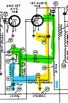
Use a 500K Pot (Linear taper would be best but Audio taper would work) with a power switch (The original "Tone Switch" was also the power switch). Add the yellow section to the circuit. Use a 0.003 uF cap between the triode plate of the 6Q7 1st Audio Amp and the "Full CW leg of the tone control. The center (wiper) terminal goes to Chassis Ground. Connect the Full "CCW" leg of the tone control to the junction of Cap #43 and Resistor #45.
"Do Justly, love Mercy and walk humbly with your God"- Micah 6:8
"Let us begin to do good"- St. Francis
Best Regards,
MrFixr55
Posts: 5,652
Threads: 56
Joined: Sep 2008
City: Sandwick, BC, CA
Mr. Fix;
I think you mean the 7C6 rather then the 6F6 plate, at least in the setup above, I would also use a safety cap as I have found one or two instances of that coupling cap shorting and burning up the tone control. The last was in a set with concentric tone, and volume controls, with power switch, and those are harder to find then the stand alone ones.
Regards
Arran
Posts: 172
Threads: 10
Joined: Mar 2026
City: Franklin
State, Province, Country: Maine
While I'm waiting on some material to attempt the repair of a band switch wafer, and the subsequent final two resistor replacements, I was thinking about test equipment.
I know a dim bulb test is basically the first step once I'm reasonably certain I've gotten everything back together correctly, and so I put this together today with old things we have around/extracted from the houses here and next door:
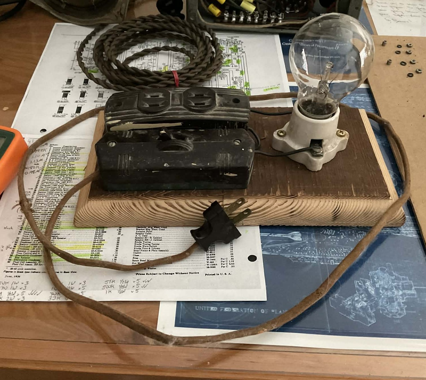
Two old surface-mount Levitons, an old porcelain bulb socket, and re-used the safe part of the radio's old power cord and plug. The wiring between the devices is the only "new" stuff - decided not to try reusing the old knob and tube wiring. The board is cut from one of the 140 year old subfloor boards from the house that was removed, replaced, and kept aside a few years back. No idea about the age of the bulb, but I'm thinking it's up there too - still works though. This one is a 60 watt bulb, though. According to the specs, the 37-620 uses 65 watts. What wattage bulbs would you say are ideal for testing once at that stage? As I understand it, to truly test for a short, I should be trying a bulb which itself is a higher wattage than the radio to see if it goes super bright and stays that way, but I'm also thinking a super-high wattage is bad for the radio if there is actually a short?
I've also been looking at some variacs online. Most people seem to think that's a pretty essential piece as well - agree/disagree? I've heard isolation transformer also, but not as universally necessary.
Looking forward further, when I'm sure the radio is electrically sound, I presume it should also be realigned. I know more tools are helpful than not, but a signal generator seems to be pretty much an absolute necessity. Are there specs or features I should be looking for?
Best wishes,
Roy
Posts: 18,427
Threads: 622
Joined: Oct 2011
City: Jackson
State, Province, Country: NJ
I let others comment on equipment; my comment on the dim bulb tester.
I am not a fan of those, but this is why we have he 1st amendment.
This said, any test equipment should be safe and should not look the way that says that it itself has to be restored.
The AC cord is old and frayed, and the open lugs for 110V wire is not exactly the epitome of safety.
People who do not drink, do not smoke, do not eat red meat will one day feel really stupid lying there and dying from nothing.
Posts: 109
Threads: 15
Joined: Mar 2024
City: BERTHOUD
State, Province, Country: CO
I don’t personally like dim bulb testers. My preference is a good isolation transformer and dialing up the voltage while monitoring B+. Also before turning anything on I have done resistance measurements on the power transformer, recapped, tested tubes, etc.
I should like dim bulb testers, since I am a dim bulb…
Craftsmanship is an ongoing cycle of learning fueled by patience, persistence, and care, where every project refines our judgment and challenges our skills, in the steady pursuit of the Path to Mastery.
Posts: 18,427
Threads: 622
Joined: Oct 2011
City: Jackson
State, Province, Country: NJ
If you don't like it, make it a museum display, but don't use it.
You are right, a Variac is what is a right tool, and, yes, an isolation transformer.
People who do not drink, do not smoke, do not eat red meat will one day feel really stupid lying there and dying from nothing.
Posts: 2,327
Threads: 23
Joined: Jul 2020
City: Greenlawn
State, Province, Country: NY
Hi Arran,
No, I did mean the 6F6. The original tone control switch varied the amount of capacity between the 6F6 plate and cathode. My proposal was to replace that with a single cap (which must be done to prevent parasitic oscillation) between the 6F6 plate and cathode (which is at chassis ground potential), have no switch or pot in series with that cap, and vary the tone by varying the capacity across the 7C6 (or similar) 1st AF stage This is what is done in more modern sets such as the 41-255 that the schematic was pulled from. The coloring on the schematic was to illustrate the 3 different paths. The green path is the audio path which is left undisturbed. The yellow path is the cap added to the 1st AF Plate to one leg of the tone control. This is much less stressful on the tone pot than varying the resistance between ground and a cap to the 6F6 plate, and is the standard tone control setup in more modern sets. The wiper is at chassis ground potential. The "Blue" path shorts out a cap that is in the input circuit whose effect is governed also by the setting on the loudness control. The extra bonus is that when reviewing the schematic for the 37-620, the parts in blue actually exist in that set and connect to one contact on the tone switch, making the mod that I am proposing to be a perfect fit for this set.
Compare my "Mod" to the original schematic for the 37-620.
Re the "Vintage" dim bulb tester, the bulb appears to be modern. However, remember that modern is anywhere from about 1930 on. You can start with a low wattage bulb and when you think that you are OK, you can go to a higher wattage bulb. Some folks make dim bulb testers with multiple sockets and switches. A poor man's Variac.
Do resecure the wires on the socket, it seems to be not completely under the screw. A little electrical RTV over the connections on the cleat type socket and replacement of the vintage power cord if bad will make it safer. No guts, no glory.
BAD JOHN!!!
"Do Justly, love Mercy and walk humbly with your God"- Micah 6:8
"Let us begin to do good"- St. Francis
Best Regards,
MrFixr55
Posts: 172
Threads: 10
Joined: Mar 2026
City: Franklin
State, Province, Country: Maine
Okay, given the feedback, we'll take the dim bulb tester out of discussion. I understand the positions that have been expressed and respect the experience that informs them.
That said, I still would appreciate guidance on what makes a "good" variac, isolation transformer, signal generator, etc. for my purposes. I doubt there is one-size-fits-all, and even if it were, I doubt it would be ideal for all applications. I see a lot of options on eBay, for example, but have no way to discern what fits the needs of this kind of project or not. I don't feel that as an entry-level hobbyist (if I even qualify for that status) I need multi-thousand-dollar tools mint out of the box, but I also don't want garbage.
"monitoring the B+" - I wish I didn't have to ask this, since I'm sure this is second hand to anyone with experience, but I'm new to this, so I need a little more explicit description about what this involves, how to do it, and with what tool. I don't have a tube tester, but again, this radio was serviced and functional, though not completely recapped, by a shop about 20 years ago, so my belief is that the tubes remain, likewise, functional. As for measuring resistance on the power transformer, as with monitoring the B+, I'm afraid I need more information.
And as before, this testing will absolutely be done following the replacement of the final two resistors. The capacitors have all been replaced at this point, except micas/semi-fixed. Bakelites were restuffed per Mike's tutorial and it was perfectly straightforward, so thumbs up there. Per other suggestions, the power switch is now between the power cord and the first capacitors in-circuit (Bakelite), and an inline fuse on the hot side between the power cord and power switch. Power cord is new retro-style, and I've also replaced the wiring from chassis to speaker, as that had crumbly and/or chewed patches in the insulation/sheathing.
Best wishes,
Roy
Users browsing this thread: 1 Guest(s)
|
|
Recent Posts
|
|
Philco P45-6365 Universal Transformer Instruction Manual
|
| Can anyone guide me to where this may be found?GRG — 03:00 PM |
|
54C Complete Teardown/Rebuild
|
| I don't think that I have encountered a 12Z3 before, curious how it uses one of those but includes a #43, which is a 25 ...Arran — 02:17 PM |
|
HiFi (Chifi) tube amp build - but my own design.
|
| It's the other forum. I'm also in DIY, but mostly read there. Honestly, I kinda jumped into this without much thought to...TV MAN — 10:43 AM |
|
Philco 71 Code 125
|
| Hello,
I am in need of a schematic for this radio. Mine has the three separate circular tube shields and a shadow me...dconant — 08:06 AM |
|
Stromberg Carlson 1500 Squeal
|
| And life just keeps getting more complicated.dconant — 07:57 AM |
|
54C Complete Teardown/Rebuild
|
| Hello Roy,
here is this one
sincerely Richardradiorich — 12:45 AM |
|
54C Complete Teardown/Rebuild
|
| Richard,
Had grabbed it already but thank you just the same. I find myself wanting to find some way to block out the...glyphmon — 12:03 AM |
|
54C Complete Teardown/Rebuild
|
| Hello roy,
here is a link to the schematic .
Sincerely Richardradiorich — 11:54 PM |
|
54C Complete Teardown/Rebuild
|
| Richard,
The Silvertone 2014 also is a transformerless set, so I am incorporating a 1:1 600 ohm audio isolation transfo...glyphmon — 11:37 PM |
|
Preliminary work on wife's Silvertone 2014
|
| Did an alignment today which was interesting. IF alignment went great, almost all was already spot-on. Adjusting on th...glyphmon — 11:35 PM |
|
Who's Online
|
There are currently 1815 online users. [Complete List]
» 2 Member(s) | 1813 Guest(s)
|
|
|

|
 
|