Posts: 90
Threads: 32
Joined: Oct 2011
City: Nipomo
State, Province, Country: CA
Hi everyone,
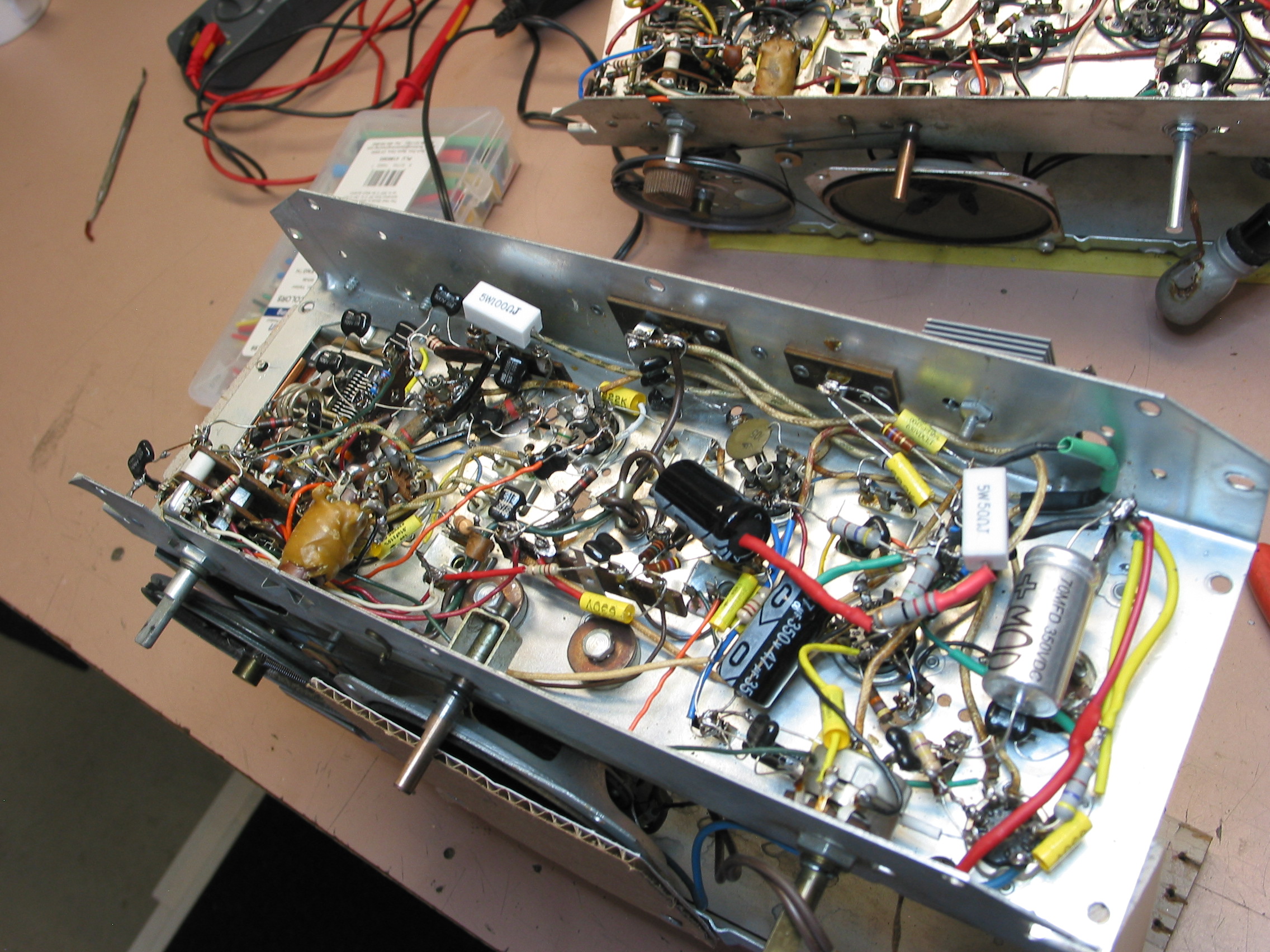
I have a Philco 52-944 that I recently re-capped and can’t get a signal out of it. Hopefully someone can give me a tip as to what I’m missing. I may hear a faint crackle or hum in the speaker but no radio signal coming thru. I have checked everything that I could think of, tubes, transformers, tuner, I retraced the schematic, checked continuity throughout the band selector. I even have a 53-958 that I compared wiring. Now here’s the big clue, I replaced the selenium rectifier with a diode and adjusted the following resistor to get the 130v (not what I expected, 15ohm gave me 132v), the 120v called for at the 70mf electrolytic was 116v, but then the voltage at the 3rd electrolytic was only about 40v and the preceding 470 ohm resistor gets blistering hot.
Can you help lead me in some direction?
Thanks,
Alan
Posts: 3,186
Threads: 226
Joined: May 2008
City: Omak
State, Province, Country: WA
Hello Alan,
First all that radio looks great so far !
So C38B 40ufd capacitor ?
What i would do with no power applied is to take some resistance readings to make sure there is no shorts and check every tube again it sounds like Audio amp section could where the issue lays it looks like you replaced a lot of resistors and Mica capacitors double check and triple check everything .
Sincerely Richard
Posts: 90
Threads: 32
Joined: Oct 2011
City: Nipomo
State, Province, Country: CA
Thanks Richard, the 470 ohm resistor will burn if I don't shut it down. There's a lot of bad or no voltage readings that I don't understand. I think at one point I fed an audio signal into it and got it clear so I don't think the problem is in the output section. What would cause that resistor to burn?
Alan
Posts: 3,186
Threads: 226
Joined: May 2008
City: Omak
State, Province, Country: WA
Hello AlaN,
Excessive current draw will cause that resistor to get really hot !
One the first things that I would do is to take a resistance reading but make sure you have no power applied measure the resistance from R26 and C38B junction also check all of your wires go through the schematic and look at everything that is feed from C38B one by one check everything!
Sincerely Richard
Posts: 1,135
Threads: 54
Joined: Feb 2013
City: Shenandoah,
State, Province, Country: Pennsylvania
Hi Alan, just a thought here. If originally the 470 ohm resistor wasn’t burned, then possibly the new 40mfd cap C38b could be bad or you have the + and - reversed, that would surely load down the 110V B+ and overheat that resistor.
Ron
Bendix 0626. RCA T64 Philco 20B
Philco 41-250. Philco49-500
GE 201. Philco 39-25
Motorola 61X13. Philco 46-420 Crosley 52TQ
Philco 37-116. Philco 70
AK 35 Philco 46-350
Philco 620B. Zenith Transoceanic B-600
Philco 60B. Majestic 50
Philco 52-944. AK 84
(This post was last modified: 08-01-2022, 08:02 AM by 462ron.)
Posts: 90
Threads: 32
Joined: Oct 2011
City: Nipomo
State, Province, Country: CA
Thanks Ron, I have checked polarity, but I hadn't thought about swapping out that electrolytic. I'll give it a try. Then I guess I better trace out the schematic, again.
Alan
Posts: 3,186
Threads: 226
Joined: May 2008
City: Omak
State, Province, Country: WA
Hello Alan,
That is a good idea what Ron pointed out !
Sincerely Richard
Posts: 90
Threads: 32
Joined: Oct 2011
City: Nipomo
State, Province, Country: CA
Swapped out the 38B 40mfd electolytic and the diode too, no change. In process retracing the schematic.
Alan
Posts: 1,797
Threads: 55
Joined: Feb 2015
City: Roseville, MN
Hi Alan,
Check the hot 470 ohm resistor on AM and FM. The 110 volts DC is feeding FM plate circuits as well as audio screens so maybe if it doesn't get hot when AM is selected you can eliminate some circuitry.
Posts: 90
Threads: 32
Joined: Oct 2011
City: Nipomo
State, Province, Country: CA
Thanks, haven't thought of that. On AM band I just watched the 470 ohm, 2 watt resistor fade color then the casing began to melt. Not sure about the FM, but I can scratch out any FM circuitry that is isolated by the band selector and reduce the circuitry to look at.
I'm starting to get a feeling about the IF transformers. My trouble started when I damaged Z1 and got a replacement from another radio. Finding the radio dead I replaced Z2 so I had a pair from the loaner 51-934. Their terminals have green and pink dots that don't always agree with the schematic, even one that I never removed. I get good ohm readings so the transformers are probably good, but there may be a wiring problem there. I get a headache if I stare at these too long.
Alan
Posts: 3,186
Threads: 226
Joined: May 2008
City: Omak
State, Province, Country: WA
Hello Alan,
I think you may have found your area where the problem lays !
Sincerely Richard
Users browsing this thread: 1 Guest(s)
|
|
Recent Posts
|
|
Philco 71 Code 125
|
| Hello,
I am in need of a schematic for this radio. Mine has the three separate circular tube shields and a shadow me...dconant — 08:06 AM |
|
Stromberg Carlson 1500 Squeal
|
| And life just keeps getting more complicated.dconant — 07:57 AM |
|
54C Complete Teardown/Rebuild
|
| Hello Roy,
here is this one
sincerely Richardradiorich — 12:45 AM |
|
54C Complete Teardown/Rebuild
|
| Richard,
Had grabbed it already but thank you just the same. I find myself wanting to find some way to block out the...glyphmon — 12:03 AM |
|
54C Complete Teardown/Rebuild
|
| Hello roy,
here is a link to the schematic .
Sincerely Richardradiorich — 11:54 PM |
|
54C Complete Teardown/Rebuild
|
| Richard,
The Silvertone 2014 also is a transformerless set, so I am incorporating a 1:1 600 ohm audio isolation transfo...glyphmon — 11:37 PM |
|
Preliminary work on wife's Silvertone 2014
|
| Did an alignment today which was interesting. IF alignment went great, almost all was already spot-on. Adjusting on th...glyphmon — 11:35 PM |
|
54C Complete Teardown/Rebuild
|
| The main problem with adding a Bluetooth input is that this set lacks a traditional power transformer to isolate it from...radiorich — 11:19 PM |
|
54C Cabinet Refinish
|
|
I started stripping this cabinet before it got super chilly out because I knew I wasn't going to be able to work on ...glyphmon — 11:18 PM |
|
54C Complete Teardown/Rebuild
|
| While I'm waiting to wrap up the final steps on my wife's Silvertone 2014, I started disassembly on the next project. O...glyphmon — 11:07 PM |
|
Who's Online
|
There are currently 1267 online users. [Complete List]
» 2 Member(s) | 1265 Guest(s)
|
|
|

|
 
|





