01-21-2025, 01:43 PM
Hi Phil,
Sorry for joining this thread late. Hopefully I am adding to the conversation.
First off, Welcome to the Phorum! You have some very talented people helping you.
Secondly, I think that this will be a great sounding radio! This is a nice radio, ca 1933-1934 with a triode push pull output. I am guessing that the output is 5Watts or so if it is Clas A or 10 watts if Class AB2. Considering that there is a 6F6 Driver, I am thinking AB 2. The radio has a separate oscillator and mixer and covers from broadcast to 22MHz in 4 bands.
Thirdly, re the electrolytics, this is a rather complex situation. I believe that, based on how it was mounted, the Tobe branded cap (we usually refer to capacitors and condensers as "caps" as shorthand) was a replacement, and likely not done correctly. In addition, the blue 2 section cap by the wirewound resistor, 90, is also a replacement, put in parallel with one section of Cap 73. Just cut this out. Looking at your pics, in Post 7 and the last 2 pics, the opening in the lower right hand corner housed 2 electrolytic caps, #91 and #98. #98 is a single 8uF cap. Cap #91 was a dual cap of 10 and 12 uF with a common negative connected to the can of the cap. The can of both of these caps were insulated from the chassis The connections must be made correctly. This bears discussion.
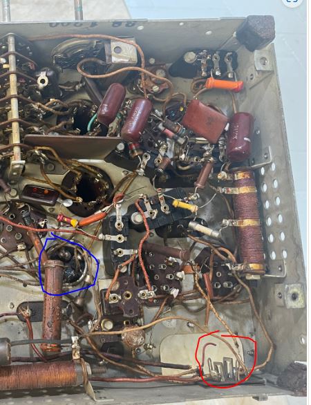
Attached below is a copy of one of your pictures. The red circle shows the original location of Cap # 91. Please note that the red circle is not indicating the speaker jack, it is locating the area above the speaker jack. Cap # 98 would have been next to it. The blue circle is Cap # 73. This cap is an electrolytic cap, not an oil cap and it should be replaced.

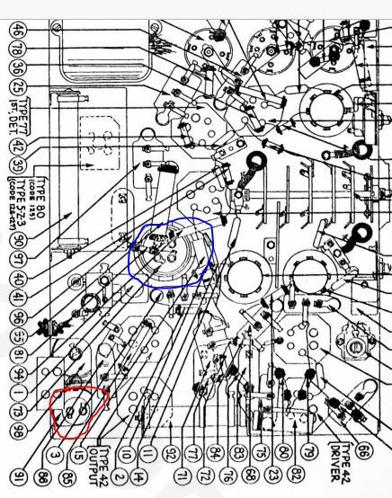
The attachment below is the pictorial of the chassis from the service documentation. As above, the red circle denotes Cap #91, the blue circle encompasses Cap # 73

Looking at the schematic, it is important to note that Ground is not the most negative point in the power supply. The center tap of the HV secondary of the power transformer is the most negative point. This is very common with radios from the 1930s. Chassis ground was considered B- and C+. The HV secondary center tap was considered "C-", the grid bias source for the power amp tubes. However, this is a matter of semantics; the radio is really cathode biased as opposed to fixed bias. Since the chassis has been modified (the mounting tab for the clamps for Caps 91 and 98 were hacked off) replace these 2 caps with 3 separate caps.
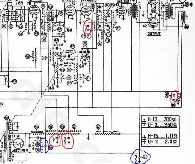
Attached below is a copy of the section of the schematic which contains Caps 98, 91 and 73. The 2 caps comprising Cap #91 are circled in red. The 4 caps comprising Cap # 73 are circled in blue. OOPS- The 2 caps that comprise Cap #91 are circled in blue. The 4 caps that comrrise Cap # 73 are in red. (I am nothing if not consistently inconsistent.) Hopefully, this makes the next instructions more simple:

Cap 98 is straight forward. Use a 10 uF cap, connected per the schematic. The positive (+) terminal of this cap connects to the junction of the 80 Rectifier filament and the input of the filter choke, #96. The negative (-) terminal of this cap connects to the center tap of the HV secondary of the power transformer.
Cap 91 is a little more complex. Use 2 separate caps. For the 1st cap, use a 10 or 12 uF cap and connect the positive (+) terminal connects to the junction of the output of the filter choke #96, the speaker field connection and several resistors. The negative (-) terminal of this cap also connects to the HV secondary center tap of the power transformer. Finally, for the second section of Cap #91, Use a 10 uF cap. Connect the positive (+) lead of this cap to Chassis ground and the negative (-) lead to the center tap of the HV secondary of the power transformer.
Finally, there is another 4 section cap, # 73 on the Schematic and on the Pictorial. The easiest way of handling this cap is to remove the connections form the original cap and install 2 solder type terminal posts to handle 3 separate caps of 1.0uF and one cap of 2.0uF. If these are electrolytic, use 450V caps. If mylar then use 630V caps. Do not attach the replacement caps directly across the terminals of the original caps. This is called bridging and is a poor practice. The original electrolytic may be open but it could also short, arc, etc., all of this being bad. Some restorers like to "stuff" the original cap (cut the cap open, remove the original contents and install new caps within the original can). This is not easily done but is aesthetically pleasing. This can be done with Cap #73 because it exists on your chassis. To "stuff" Caps 91 and 98, you need something to stuff and the hardware to mount the stuffed caps, and you need to add metal to the chassis.
Sorry for joining this thread late. Hopefully I am adding to the conversation.
First off, Welcome to the Phorum! You have some very talented people helping you.
Secondly, I think that this will be a great sounding radio! This is a nice radio, ca 1933-1934 with a triode push pull output. I am guessing that the output is 5Watts or so if it is Clas A or 10 watts if Class AB2. Considering that there is a 6F6 Driver, I am thinking AB 2. The radio has a separate oscillator and mixer and covers from broadcast to 22MHz in 4 bands.
Thirdly, re the electrolytics, this is a rather complex situation. I believe that, based on how it was mounted, the Tobe branded cap (we usually refer to capacitors and condensers as "caps" as shorthand) was a replacement, and likely not done correctly. In addition, the blue 2 section cap by the wirewound resistor, 90, is also a replacement, put in parallel with one section of Cap 73. Just cut this out. Looking at your pics, in Post 7 and the last 2 pics, the opening in the lower right hand corner housed 2 electrolytic caps, #91 and #98. #98 is a single 8uF cap. Cap #91 was a dual cap of 10 and 12 uF with a common negative connected to the can of the cap. The can of both of these caps were insulated from the chassis The connections must be made correctly. This bears discussion.
Attached below is a copy of one of your pictures. The red circle shows the original location of Cap # 91. Please note that the red circle is not indicating the speaker jack, it is locating the area above the speaker jack. Cap # 98 would have been next to it. The blue circle is Cap # 73. This cap is an electrolytic cap, not an oil cap and it should be replaced.
The attachment below is the pictorial of the chassis from the service documentation. As above, the red circle denotes Cap #91, the blue circle encompasses Cap # 73
Looking at the schematic, it is important to note that Ground is not the most negative point in the power supply. The center tap of the HV secondary of the power transformer is the most negative point. This is very common with radios from the 1930s. Chassis ground was considered B- and C+. The HV secondary center tap was considered "C-", the grid bias source for the power amp tubes. However, this is a matter of semantics; the radio is really cathode biased as opposed to fixed bias. Since the chassis has been modified (the mounting tab for the clamps for Caps 91 and 98 were hacked off) replace these 2 caps with 3 separate caps.
Attached below is a copy of the section of the schematic which contains Caps 98, 91 and 73. The 2 caps comprising Cap #91 are circled in red. The 4 caps comprising Cap # 73 are circled in blue. OOPS- The 2 caps that comprise Cap #91 are circled in blue. The 4 caps that comrrise Cap # 73 are in red. (I am nothing if not consistently inconsistent.) Hopefully, this makes the next instructions more simple:
Cap 98 is straight forward. Use a 10 uF cap, connected per the schematic. The positive (+) terminal of this cap connects to the junction of the 80 Rectifier filament and the input of the filter choke, #96. The negative (-) terminal of this cap connects to the center tap of the HV secondary of the power transformer.
Cap 91 is a little more complex. Use 2 separate caps. For the 1st cap, use a 10 or 12 uF cap and connect the positive (+) terminal connects to the junction of the output of the filter choke #96, the speaker field connection and several resistors. The negative (-) terminal of this cap also connects to the HV secondary center tap of the power transformer. Finally, for the second section of Cap #91, Use a 10 uF cap. Connect the positive (+) lead of this cap to Chassis ground and the negative (-) lead to the center tap of the HV secondary of the power transformer.
Finally, there is another 4 section cap, # 73 on the Schematic and on the Pictorial. The easiest way of handling this cap is to remove the connections form the original cap and install 2 solder type terminal posts to handle 3 separate caps of 1.0uF and one cap of 2.0uF. If these are electrolytic, use 450V caps. If mylar then use 630V caps. Do not attach the replacement caps directly across the terminals of the original caps. This is called bridging and is a poor practice. The original electrolytic may be open but it could also short, arc, etc., all of this being bad. Some restorers like to "stuff" the original cap (cut the cap open, remove the original contents and install new caps within the original can). This is not easily done but is aesthetically pleasing. This can be done with Cap #73 because it exists on your chassis. To "stuff" Caps 91 and 98, you need something to stuff and the hardware to mount the stuffed caps, and you need to add metal to the chassis.
"Do Justly, love Mercy and walk humbly with your God"- Micah 6:8
"Let us begin to do good"- St. Francis
Best Regards,
MrFixr55


![[-] [-]](https://philcoradio.com/phorum/images/bootbb/collapse.png)


