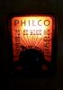
Philco Model 38-7: what caps & resistors do fail typically?
Posts: 16
Threads: 1
Joined: Jun 2025
City: Montreal
State, Province, Country: Quebec
Hi all,
on vacation in Montreal, a friend of mine showed me a Philco Model 38-7 console radio from the 30ies. Mechanically very sound, all original, complete, couldn't resist offering him to look after the electronics.
Now I have the chassis and the loudspeaker. I have some tools at hand (scope, multimeter, soldering iron), but no components and no variac /isolation transformer, making repair a bit tricky. Can anybody help me about what caps and resistors typcially always fail in these units? So I can do some focused shopping...
If some good soul would welcome me in his workshop in Montreal that would be great, too :-)
I'm a german electronics engineer and like to repair old stuff, TVs, Radios, measuring equipment, audio stuff... here is the most recent: https://groups.io/g/TekScopes/message/209892
cheers
Martin
Posts: 5,584
Threads: 291
Joined: Nov 2012
City: Wilsonville
State, Province, Country: OR
Welcome to the Phorum!

Here's the schematic for that radio from our digital library: https://philcoradio.com/library/download...l.%202.pdf
Something to do before you start replacing caps is to check the continuity of all the various transformer coils. If one of those is open you have a bigger job than just replacing caps.
The electrolytic caps and all the paper caps will be bad and will need replacing. Resistors need to be checked to determine which are out of spec. Mica caps are usually OK.
Posts: 2,263
Threads: 164
Joined: Jan 2013
City: Westland, MI
Welcome to the Phorum, Martin! Open a new thread in Philco Electronic Restoration when you begin working on your 38-7. Lots of folks here to help you along. Post your photos and questions there. Take care, - Gary
"Don't pity the dead, pity the living, above all, those living without love."
Professor Albus Dumbledore
Gary - Westland Michigan
Posts: 16
Threads: 1
Joined: Jun 2025
City: Montreal
State, Province, Country: Quebec
Good idea to check the coils... then I'll get hold of an incadescent light bulb and see what happens when the unit is switched on in series with the bulb.
I've found 3 electrolytic caps in the schematics, 2 X- (or Y-?) caps across the mains, and a bunch of paper caps mainly around the volume control.
cheers
Martin
Posts: 5,584
Threads: 291
Joined: Nov 2012
City: Wilsonville
State, Province, Country: OR
Yep the dim bulb test is OK but I'd definitely replace all those electrolytics before I did it. Since those #47 condensers each go to ground I would replace with Y safety caps. The #47 condenser is a 3793DG bakelite block capacitor. I've only seen this style in Philco's but its essentially a paper capacitor also. Here's a tutorial for taking the old caps out of that block and replacing with new ones although I'm not certain whether 2 new style Y caps will fit or whether you are trying to retain the look of the electronics or just replacing with new caps. (Restoration vs repair?) https://philcoradio.com/library/index.ph...soldering/
...and here's some wiring data on those block capacitors: https://philcoradio.com/library/index.ph...lock-data/
I usually take the block out of the set completely in order to remove the old cap and stuff in a new one.
Posts: 1,797
Threads: 55
Joined: Feb 2015
City: Roseville, MN
Welcome to the Phorum Martin.
I count about 9 paper caps, the 3 electrolytic caps and 2-Y2 safety caps to replace the line filter caps inside part 47 bakelite block.
Posts: 3,186
Threads: 226
Joined: May 2008
City: Omak
State, Province, Country: WA
Hello Martin,
Welcome aboard our little community what great Model 38-7
Sincerely Richard
Posts: 2,263
Threads: 164
Joined: Jan 2013
City: Westland, MI
Since you stated earlier, you have a console 38-7XX. They also had a 38-7T (table), and 38-7CS (chairside). A very nice radio indeed! Take care, - Gary
"Don't pity the dead, pity the living, above all, those living without love."
Professor Albus Dumbledore
Gary - Westland Michigan
Posts: 5,652
Threads: 56
Joined: Sep 2008
City: Sandwick, BC, CA
I would make one suggestion before you start working on a tube radio, or TV, with a steel chassis, pick up a larger iron of between 100 to 200 watts, or something in-between. I see people in videos try to make connections to a chassis, or other large metal part, using a pencil iron from soldering station, usually making a pigtail with the old lead in some way, and it makes me cringe. It's not so much the temperature as the mass of the iron's tip. If you look around at thrift stores, flea markets, and garage sales you can usually find a bigger iron, if you would like a new one a place that sells stained glass tools is good, and they have good soldering iron stands to go with them.
Since you are in Montreal there are a few electronic parts liquidators in the area, such as Addison and Maddison, if they are still in business, if not Digikey and Mouser sell a lot of what you need. WJOE Radio is good for paper cap replacements, and their electrolytics are not bad either, though they don't have as much for resistors as Digikey, and Mouser.
Regards
Arran
Posts: 16
Threads: 1
Joined: Jun 2025
City: Montreal
State, Province, Country: Quebec
Posts: 18,427
Threads: 622
Joined: Oct 2011
City: Jackson
State, Province, Country: NJ
I recommend not questioning what fails and what doesn't:
- All paper caps fail. All. Period. Yank and replace.
- All electrolytics fail.
- All resistors are to be checked and replaced as needed (20% tolerance is OK).
Don't fail
- Mica caps. Only replace if damaged. Only check (open circuit, de-solder on lead only) if thee circuit does not work and there is no other good explanation. That is, leave alone unless really have to check.
People who do not drink, do not smoke, do not eat red meat will one day feel really stupid lying there and dying from nothing.
Posts: 1,797
Threads: 55
Joined: Feb 2015
City: Roseville, MN
The schematic shows 3 wires running to the speaker. Your speaker has 2 coils, one is the voice coil that makes the cone move and the other is the field coil magnet that creates the magnetic field so the voice coil can do it's thing. In addition the output transformer is also mounted on the speaker basket. The field coil is typically the choke coil in the power supply. If you look at the schematic, it shows the field coil in the power supply filter circuit. The B+ output voltage from this power supply is connected to the primary winding of the output transformer; this is one wire. The other end of the output transformer primary is the other wire and the third wire is the other end of the field coil. Very dangerous voltages running external from chassis to speaker.
Posts: 16
Threads: 1
Joined: Jun 2025
City: Montreal
State, Province, Country: Quebec
Oh, thats why I could not find the choke on the layout. Thanks RodB!
I changed the power cord. Checked resistances. Since everything looked original and in physically good condition I decided to see what happens if I put some voltage on the mains. With a 40W bulb in series, quickly after switch-on I got readings over 200 volts on the B+ supply, dropping to 100 volts after a while. A very faint noise was audible from the speaker, and with antenna I could receive a station.
So I moved on. With a 60W bulb I got good volume and all voltages from the manual are coherent. Could receive a dozen stations with a wire on the antenna. With a 100W bulb I was able to disturb the neighbors...  Nothing gets particularly warm. B+ is somewhat below 300 volts.
Thats where I am right now. I apologize for not having listened to all those who suggest to change caps first. I know that this set must not be used in this condition, but its nice to see that not much is at fault. I think the most urgent is the Y-caps on the mains, and check the electrolytics. From then on, if it works and voltages are correct, it should be OK for sporadic & supervised use.
The power switch with its 4 positions seems to modify tonality... couldn't find this in the manual (yet). The leftmost position should be "off", I guess. It does not switch off immediately, only after moving the know a bit in the opposite direction. Is this switch serviceable?
cheers
Martin
Posts: 1,797
Threads: 55
Joined: Feb 2015
City: Roseville, MN
Looking at the schematic you'll see a dashed line starting with the power switch running to the right to the tone control circuit switch. The dashed line indicates the switches are physically linked to the same shaft. Examine it for small openings and spray contact cleaner into the switch. Then work the switch back and forth many times.
I also noticed the line filter is wired to the wrong side of the power switch. After replacing the line filter caps, move that connection in to the other side of the switch. Now the line filter will only have power when the switch is on. Make sense? I've seen several line filters blown apart because whenever the set is plugged in there's power on the caps.
Posts: 1,797
Threads: 55
Joined: Feb 2015
City: Roseville, MN
On those two parts you pointed out earlier, I can't tell what they are. Perhaps you can tell us where the wires on them are connected in the circuitry.
Users browsing this thread: 3 Guest(s)
|
|
Recent Posts
|
|
Philco P45-6365 Universal Transformer Instruction Manual
|
| Can anyone guide me to where this may be found?GRG — 03:00 PM |
|
54C Complete Teardown/Rebuild
|
| I don't think that I have encountered a 12Z3 before, curious how it uses one of those but includes a #43, which is a 25 ...Arran — 02:17 PM |
|
HiFi (Chifi) tube amp build - but my own design.
|
| It's the other forum. I'm also in DIY, but mostly read there. Honestly, I kinda jumped into this without much thought to...TV MAN — 10:43 AM |
|
Philco 71 Code 125
|
| Hello,
I am in need of a schematic for this radio. Mine has the three separate circular tube shields and a shadow me...dconant — 08:06 AM |
|
Stromberg Carlson 1500 Squeal
|
| And life just keeps getting more complicated.dconant — 07:57 AM |
|
54C Complete Teardown/Rebuild
|
| Hello Roy,
here is this one
sincerely Richardradiorich — 12:45 AM |
|
54C Complete Teardown/Rebuild
|
| Richard,
Had grabbed it already but thank you just the same. I find myself wanting to find some way to block out the...glyphmon — 12:03 AM |
|
54C Complete Teardown/Rebuild
|
| Hello roy,
here is a link to the schematic .
Sincerely Richardradiorich — 11:54 PM |
|
54C Complete Teardown/Rebuild
|
| Richard,
The Silvertone 2014 also is a transformerless set, so I am incorporating a 1:1 600 ohm audio isolation transfo...glyphmon — 11:37 PM |
|
Preliminary work on wife's Silvertone 2014
|
| Did an alignment today which was interesting. IF alignment went great, almost all was already spot-on. Adjusting on th...glyphmon — 11:35 PM |
|
Who's Online
|
There are currently 2118 online users. [Complete List]
» 1 Member(s) | 2117 Guest(s)
|
|
|

|
 
|