42-327 heater circuit confusion
Posts: 20
Threads: 2
Joined: Oct 2025
City: Springfield
State, Province, Country: Missouri
Hello, I’m new to this forum and have a couple of Philco radios that I’ve been working on. Currently it’s the 42-327 122, it seems that whoever was here before me made some adjustments and aside from the 80 ohm heater resistor missing I’m having to assume it’s the 122 because other wiring matches both the 121 and 122. I need help in sorting this circuit. When plugged in there is no power to the heaters but there is power to the switch and it checks ok. The 35z3 heater checks ok and shows no sign of a short. I’m guessing the x means that wire is taken out and replaced with the dotted line configuration and so I’ve been checking all those changes. Some are right for the 122 and some are right for the 121. The radio was not working when I got it and I had to replace the 35z3 loctal socket and a lot of crumbling wiring. So, now I’m not sure if I want to power it on or continue tracing the wiring, but first I need confirmation about the heater circuit as I read the schematic. Field coil, speaker and resistors are not too far out of specs and most caps I have replaced. Thanks
Posts: 18,427
Threads: 622
Joined: Oct 2011
City: Jackson
State, Province, Country: NJ
OK, so with the 80 Ohm missing there should be other things too, like yje pilot lamp circuit, the 35Z5 connection.
Just trace it.
Now, the power to the heaters: I am not sure if this means "the heaters do not light up" or something else.
If the forme, keep in mind, that ANY filament being bad (open; it is almost bever short; filaments burn and open. Like ina lightbulb) will result in exactly this: no filaments light up.
1. Take out the tube, check EVERY filament for continuity. If you got no tube tester, use a multimeter. It is usually in tens of Ohms for 7-volt tubes. But there should be a reasonable (a few hunderd Ohm for a 50V tube to tens for 6-7V one) resistance.
2. Check your wiring. It is a daisy-chain.
3. I all is OK, clean (sandpaper, scalpel) your pins. Loctal are known for bad, bad oxidation.
4. Might as well clean the sockets. Be gentle. Careful application of Deoxit D5 (or a good contact cleaner) helps. Don't just spray it around, target to pins. or even put some in a small aluminum cup, use a sharp toothpick to dip in it and then push into pins' sockets.
Let dry before re-powering.
PS. It is a "warm" chassis set. Power it from an isolation transformer. Do not connect grounded devices to it (like a scope) unless the set is plugged through such a transformer.
People who do not drink, do not smoke, do not eat red meat will one day feel really stupid lying there and dying from nothing.
Posts: 20
Threads: 2
Joined: Oct 2025
City: Springfield
State, Province, Country: Missouri
Thanks for the process, I’m working on it. I checked the tubes filaments at around 13 ohms and 48 and 35 for the output 50L and 35Z. After that I’ve been tracing my wiring against the schematic and am a little confused by the lamp circuit. When I said they don’t power I mean they don’t heat or light up. Power on B+ was near 0 at 0.6v the 35Z didn’t light up but a dim bulb tester connected to the variac shows a possible short. Tracing the B+ and B- throughout since reading your reply. I’ll clean the loctal sockets too. This was a really dirty radio, maybe a mouse hotel. I’ve got hope for it though and lots of time. A list of resistance checks from Philco would help, but I’ll go through it with the book “Elements of Radio Servicing” suggestions on ohmage.
Posts: 20
Threads: 2
Joined: Oct 2025
City: Springfield
State, Province, Country: Missouri
Thanks for the reply, I’ll be working on this for awhile. And will follow your suggestions.
Posts: 5,652
Threads: 56
Joined: Sep 2008
City: Sandwick, BC, CA
Mike;
This particular set uses a Loctal cousin of a 35Z5 called a 35Z3 which has no pilot lamp tap on the heater, these sets use a 120 volt candelabra bulb for a pilot lamp. These sets have six tubes, one is a 12.6 volt, on 35 volt tube, a 50 volt tube, and the remaining three are 6.3 volts, all at 150 ma. So 116.5 volts total, if it uses a 35Z3 it's a code 122, if it has a 35Z5 it's a code 121 both versions seem to have that 80 ohm power resistor https://philcoradio.com/library/download...20Book.pdf
Regards
Arran
Posts: 18,427
Threads: 622
Joined: Oct 2011
City: Jackson
State, Province, Country: NJ
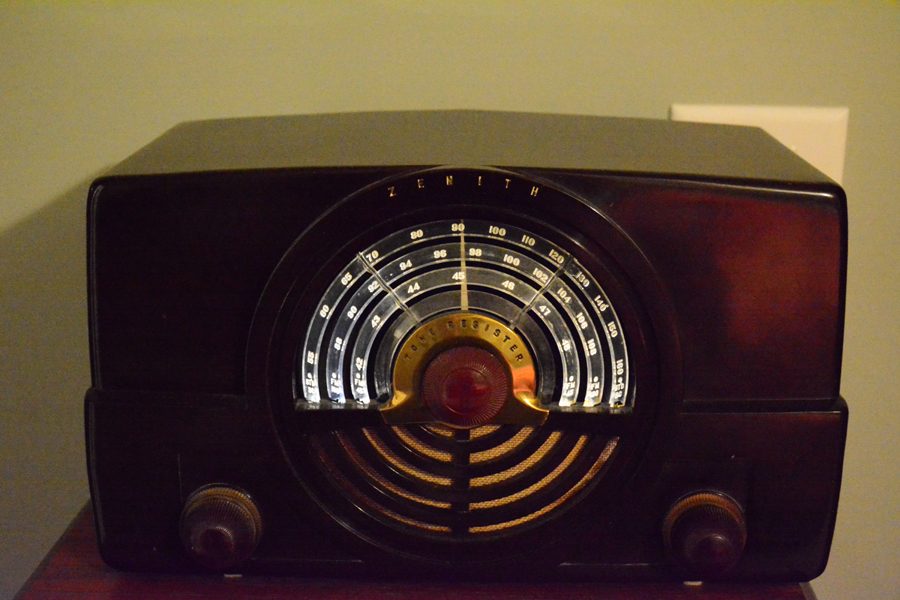
Yeah, my 7H920 Zenith also has a 120V candelabra bulb.
Had some challenge finding one for a reasonable amount, but succeeded.
You should see what this thing did to the cardboard behind it (some genius put it there; let's just say it is charred) and the lightpipe (those acrylic circles inside the dial space). Yes it was supposed to be a lightpipe. Pretty advanced for its time. But this bulb melted and browned the end that is the lightpipe's face where the light enters, and...well, it no longer can be considered a lightpipe.
People who do not drink, do not smoke, do not eat red meat will one day feel really stupid lying there and dying from nothing.
Posts: 1,222
Threads: 50
Joined: Oct 2017
City: Allendale, MI
Those lamps created a lot of heat. My 7H820 Zenith had heat damage as well. In addition, these radios used a foam sealer between the speaker and the case. Total goo! I replaced the lamp with LED's on each end of the light pipes. Allows my aging eyes to see the scales better. Not original, but more useful for me. I left the socket there for future reference.
Posts: 5,652
Threads: 56
Joined: Sep 2008
City: Sandwick, BC, CA
Mike;
I think your set used a bayonet based pilot lamp didn't it? The one in my Philco 42-327 is threaded like a night light or old style Christmas light bulb, the 46-1201 sets used the same, and there was a service bulletin about melting a blog of solder on the bracket to prevent one from pushing the bulb in too far, thus burning the screen. I think that the Philco Hippos sets used the same, along with the light pipe idea for the plastic dial, not unlike these brand Z set you fixed up.
I can remember having to rewire a good part of my 42-327, including the wires going into the IF transformers, it has three transformers, and two IF amp tubes. They are good performing sets when you get them working right, the 42-323 is the same chassis without the pushbutton bank, both were good sellers judging by how many are still around.
Regards
Arran
Posts: 20
Threads: 2
Joined: Oct 2025
City: Springfield
State, Province, Country: Missouri
The set that I have came with the z3 rectifier and without the 80 ohm resistor, no resistance wire in the heater line either. The schematic shows the 80 ohm as part 46 with a note that they only came on the 121, so I’m pretty sure it’s a 122. Plus the lamp is a screw in type so I found a 4watt 120 v that shouldn’t get too hot. The heater line was wired as shown in the schematic for the 121 meaning that the dotted line config wasn’t there and that confused me given the Z3 and lack of the 80 ohm resistor, meaning it doesn’t show when I do continuity checks from tube to tube. The heater line is wired kind of odd in the 122 where the rectifier and output are together and the lamp wiring drops in at the rect plate and jumps to heater at 7c6. Never seen that configuration before. Most of the wiring will need replacing and I’m planning on removing the IF cans to wire those too. The holes to the cans are too small to sleeve the wires coming out of the cans so will take them off to wire those them. Working on tracing the wires from the switch and plug through the filaments to get it all traced as I replace the crumbling wires and verify each wire connection. I was able to sleeve a couple of Zenith 6D614 IF cans because the chassis had enough room going into the cans for 1/8 inch cloth sleeves and they work great. There will be updates as I muddle through it all. I also have a couple of 48-472 Philco radios to work on but the wiring is in pretty good shape. Any suggestions are welcome. I’m kinda new and learning to troubleshoot radios vs modern pcb control boards is becoming a good challenge.
(This post was last modified: 01-22-2026, 07:18 AM by SlidesK.)
Posts: 2,327
Threads: 23
Joined: Jul 2020
City: Greenlawn
State, Province, Country: NY
Edited 01/22/2026 with corrections and additions.
Welcome to the Phorum, SlidesK. We are very happy to have you here and are always happy to help!
Please reread this post as I have updated it several times while you were also online.
Check your wiring, as well as the sockets. It may be useful to print the schematic and "white out" the solid wiring, the 35Z5 heater that reflects wiring used for the 35Z5 if you have a 35Z3. Pencil in the 35Z3 heater in place of the 35Z5 heater. One end of the 35Z3 heater and the plate connect to the power line. The other heater terminal connects to the 50L6.
For clarity (or at least as clear as I can draw), attached below is a copy of the schematic as modified for the Code 122 chassis. Unfortunately, many companies do not put tube pin numbers on the schematic. Philco is one of these.
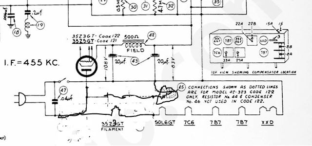
You can "ohm" across the sockets with tubes in place to check continuity between the socket pins and the tube heaters (filaments). Heater pins for the XXD, 7B7, 7C6 and almost all "loctal" tubes are pins 1 and 8. The heater pins for a 50L6 and 35W4 are 2 and 7. Once you verified that "socket" readings for heater resistance match the direct to pin readings, ohm the "heater" string from end to end, from the XXD to the 35Z3. Making these measurements should isolate the reason for no heaters.
The XXD is the Philco part number for a 14AF7. Check across the power cord with a VOM. If it lights the dimbulb, it could be a dead short. Either way, if it lights the dimbulb but the tube filaments don't light, you may be dealing with a miswiring issue.
Also, definitely check cap (capacitor) #47, across the power line and cap s #18 and#19 which connect the chassis to B-. Cap 47 likely shorts at power line voltages. Just remove it for now. Its purpose is to filter line noise. Replace Cap #47 with a Type Y "Safety Cap". Caps 18 and 19 can leak, making the chassis "hot" Don't worry about the coil around cap 19. You can try to duplicate it with wire or just eliminate it. The radio will work without the coil of wire which acts as a choke.
I dont, for the life of me know why radio manufacturers insisted in putting the switch in the "return" side (B-, "low end" of the heater string". This makes the chassis warm depending of the polarity that the plug is inserted into the outlet and whether the power switch is on or off. I install polarized power plugs on all my AC-DC sets and move the switch to the "hot" side. This makes the radio safer, but that can wait till I write a definitive article on the subject and you get the radio to work. Maybe I will do this when we get snowed in Sunday / Monday. (Not official yet but my neck o' the woods, Long Island, NY is supposed to get 12" or more of snow, then the temp is supposed to drop to 18Degrees. Oh well, 37 days till March.)
Unfortunately, most sets made in the late 1930s to early 1940s used rubber wiring which was a disaster. Newer sets used modern thermoplastics.
Good luck and keep us posted. I'm sure that you will solve this problem!
"Do Justly, love Mercy and walk humbly with your God"- Micah 6:8
"Let us begin to do good"- St. Francis
Best Regards,
MrFixr55
Posts: 18,427
Threads: 622
Joined: Oct 2011
City: Jackson
State, Province, Country: NJ
Arran,
yep it does use the bayonet-based bulb as the pilot.
People who do not drink, do not smoke, do not eat red meat will one day feel really stupid lying there and dying from nothing.
Posts: 20
Threads: 2
Joined: Oct 2025
City: Springfield
State, Province, Country: Missouri
The more I look at the comments and the heater circuit, I have to ask is pin 1 and 2 of 35Z3 is wired together on the 122? Which model has the bayonet lamp socket? Mine has a screw in socket without the 80 ohm resister. I seem to be confused where to go next, just to get the heaters wired.
(This post was last modified: 01-22-2026, 10:51 AM by SlidesK.)
Posts: 18,427
Threads: 622
Joined: Oct 2011
City: Jackson
State, Province, Country: NJ
We veered off a bit, hence the bayonet socket. Not in your radio, no.
People who do not drink, do not smoke, do not eat red meat will one day feel really stupid lying there and dying from nothing.
Posts: 2,327
Threads: 23
Joined: Jul 2020
City: Greenlawn
State, Province, Country: NY
CORRECTED AGAIN -1/23/26
Hi SlidesK,
Please reread my last post, I modified it AGAIN. Sorry, at my age (actually a little too early for me). I seem to modify my thoughts, but I did write this in the middle of the night battling insomnia.
Either Pin 1 or pin 8 (likely Pin 1) connects to the plate of the 35Z3 (pin 2) and to the center pin of the indicator lamp socket. The other heater pin (likely Pin 2) CORRECTION! (LIKELY pIN 8) connects to one of the heater pins of the 50L6 (either pin 2 or pin 7.)
Attached here are the pinouts for the 35Z3 and the drawing of the power supply (again).
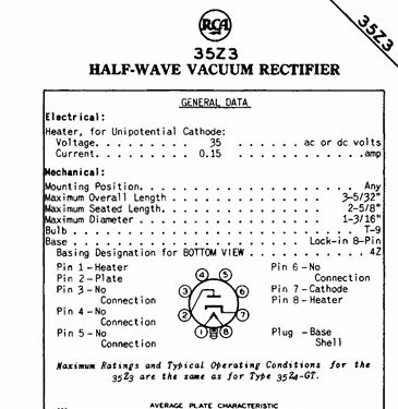
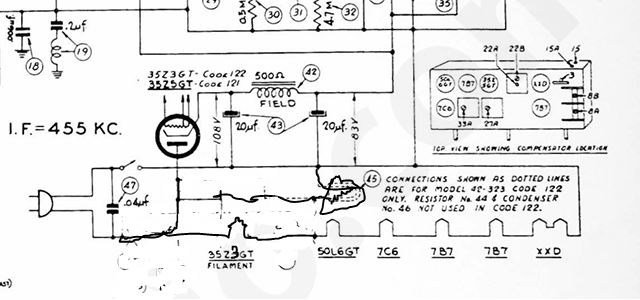
Please note that the order of pin numbering is from the bottom (worm's eye) view as from the top side (bird's eye) view.
Hope this helps!!
"Do Justly, love Mercy and walk humbly with your God"- Micah 6:8
"Let us begin to do good"- St. Francis
Best Regards,
MrFixr55
Posts: 5,652
Threads: 56
Joined: Sep 2008
City: Sandwick, BC, CA
SlidesK;
I think you are right about the 80 Ohm, resistor, but why they included it for the code 122 version only I'm not sure other then to cushion the pilot lamp bulb, and the heater tap, when you first turn the set on. It would be beneficial to the tube heaters in either version, running the voltage a little low will prolong their life as the total string only adds up to 116.5 volts, and it's normally at least 120 volts now. That would also explain why they have a paper cap connected across the pilot lamp, which is something I haven't seen before.
Regards
Arran
Users browsing this thread: 2 Guest(s)
|
|
Recent Posts
|
|
Philco P45-6365 Universal Transformer Instruction Manual
|
| Can anyone guide me to where this may be found?GRG — 03:00 PM |
|
54C Complete Teardown/Rebuild
|
| I don't think that I have encountered a 12Z3 before, curious how it uses one of those but includes a #43, which is a 25 ...Arran — 02:17 PM |
|
HiFi (Chifi) tube amp build - but my own design.
|
| It's the other forum. I'm also in DIY, but mostly read there. Honestly, I kinda jumped into this without much thought to...TV MAN — 10:43 AM |
|
Philco 71 Code 125
|
| Hello,
I am in need of a schematic for this radio. Mine has the three separate circular tube shields and a shadow me...dconant — 08:06 AM |
|
Stromberg Carlson 1500 Squeal
|
| And life just keeps getting more complicated.dconant — 07:57 AM |
|
54C Complete Teardown/Rebuild
|
| Hello Roy,
here is this one
sincerely Richardradiorich — 12:45 AM |
|
54C Complete Teardown/Rebuild
|
| Richard,
Had grabbed it already but thank you just the same. I find myself wanting to find some way to block out the...glyphmon — 12:03 AM |
|
54C Complete Teardown/Rebuild
|
| Hello roy,
here is a link to the schematic .
Sincerely Richardradiorich — 11:54 PM |
|
54C Complete Teardown/Rebuild
|
| Richard,
The Silvertone 2014 also is a transformerless set, so I am incorporating a 1:1 600 ohm audio isolation transfo...glyphmon — 11:37 PM |
|
Preliminary work on wife's Silvertone 2014
|
| Did an alignment today which was interesting. IF alignment went great, almost all was already spot-on. Adjusting on th...glyphmon — 11:35 PM |
|
Who's Online
|
There are currently 2633 online users. [Complete List]
» 2 Member(s) | 2631 Guest(s)
|
|
|

|
 
|








