Posts: 553
Threads: 89
Joined: Jun 2022
City: Marion
State, Province, Country: NY
Hello, Still messing with this radio. The 42 tube was weak and played well so I though I would just leave it be. Did not notice any appreciable hum at the time. I decided to replace the tube and now I have lots of hum. I'm pretty sure it is 60 cycle hum. The volume control has not effect on the hum, It is not the 42 tube that is the cause as I have tried 3 others. If I disconnect the wire to pin 4 (grid) of the 42 tube the hum is gone. If I touch pin for with metal object I get a hum as expected. I connected the wire back up and then disconnected the wire at the plate of the 75 tube and the hum is still present. Disconnecting the 70k (#59A) resistor at the .02 (#59) junction does not effect the hum. After disconnecting the 500k (#58) resistor the hum is gone. So this make me wonder about the 10uf (#67) ecap. I have it wire as positive ground. Is that correct? If it is then what may be the issue here. I recapped the whole radio. Also removing all tubes except the 80 and 42 make no difference. Doubling the ecaps one at time made no difference either. The one thing that bothers me is the field coil reads 678 ohms where the schematic say it is supposed to 1140. The speaker list on the Philco site says the K-32 speaker DC resistance is 435.
Dan
Posts: 553
Threads: 89
Joined: Jun 2022
City: Marion
State, Province, Country: NY
Guess I solved my own problem. I am always so careful about this but I screwed up. I wired the two 8uf caps to ground instead of the HV center tap. Quiet now.
Dan
Posts: 1,797
Threads: 55
Joined: Feb 2015
City: Roseville, MN
Now you're learning! Stay persistent. To err is human.
Posts: 553
Threads: 89
Joined: Jun 2022
City: Marion
State, Province, Country: NY
Yep. I found it using my signal tracer.
Posts: 553
Threads: 89
Joined: Jun 2022
City: Marion
State, Province, Country: NY
Still ironing out the bugs here. I did not notice right away but after I fixed the hum problem the shadow meter is not working correctly. It will close up when I tune in a station but when I move off station it takes around 10 seconds or more to spread out. I call this being lazy response. I decided to do some volt checks on the 75 tube. Well the plate voltage is supposed to be 188 but it is 260 volts. I changed 75 tubes several times with no change. So I decided to see if I could reduce the plate voltage by changing the 70k (#59A). I got the voltage down to 190 by using a 560k resistor. Yeah I know this is not the way to do it but it also resulted in my better sounding radio. I redid the alignment to see if that would help the lazy meter but no go. All the other tubes are close to what they should be. I'm using a VTVM.
Also when tuned off station it is quiet but gets noisy as you would expect when tuned off station. As the noise increases so does the meter spread out. AVC voltage changed immediately.
Any ideas?
Posts: 18,427
Threads: 622
Joined: Oct 2011
City: Jackson
State, Province, Country: NJ
I would check the V across / current through the shadograph.
See if it is the electrical or not. If you could see that the V / I disappear as soon as you detune, then it is not electrical.
You might then see if you maybe need to lube the thing or what else could delay the response. I am not sure this could be magnetic.
People who do not drink, do not smoke, do not eat red meat will one day feel really stupid lying there and dying from nothing.
Posts: 1,797
Threads: 55
Joined: Feb 2015
City: Roseville, MN
Posts: 553
Threads: 89
Joined: Jun 2022
City: Marion
State, Province, Country: NY
Volts on strong station tuned in is 4 volts when move off station I see the voltage slowly climb to 9 volts.
Current is .002 on station to .004 off station. Takes same amount of time for current to increase as volts increase.
Going from off station to on station the results of both readings is immediate.
Since I do see movement in the shadow graph it not likely to be mechanical.
If I use my signal generator as a source the current goes from 0 to .003 on/off station. Probably cause signal is stronger.
(This post was last modified: 02-28-2026, 06:43 PM by dconant.)
Posts: 18,427
Threads: 622
Joined: Oct 2011
City: Jackson
State, Province, Country: NJ
SO, does the rate of movement of the vane (shade change) coincide with the rate of voltage increase when the voltage is rising?
If yes, it is electrical.
People who do not drink, do not smoke, do not eat red meat will one day feel really stupid lying there and dying from nothing.
Posts: 18,427
Threads: 622
Joined: Oct 2011
City: Jackson
State, Province, Country: NJ
If the signal is changing slow...is your AVC reacting slow too? One of the tubes is slow to change the current, or it could be AVC which is sluggish due to wrong values of R/C or a weak tube.
Is your resistor #70 (wirewound) good, all 3 sections?
Is the 33A 1M good?
#22 2M good?
People who do not drink, do not smoke, do not eat red meat will one day feel really stupid lying there and dying from nothing.
Posts: 1,797
Threads: 55
Joined: Feb 2015
City: Roseville, MN
Hi fellas,
I believe the schematic has an error in the AVC circuit. If you look at the schematic from the library at the second IF primary to the third intersection down. It shows a connection to the AVC. This should not be a connection because there is B+ on the plate circuit of the IF. My 650X schematic has the same error. So I don't believe the AVC controls the shadow meter, it's the plate current of the 6A7.
(This post was last modified: 03-01-2026, 10:56 AM by RodB.)
Posts: 553
Threads: 89
Joined: Jun 2022
City: Marion
State, Province, Country: NY
Mike, The movement of the vane does coincide with the voltage change. The AVC voltage changes quickly. R70 has reading of 43, 27, 224 so I guess the first section is out of spec. When I first got the radio there was a wire from ground to the first section therefore making the 43 reading 0. There is no 33A resistor but I checked all the other 1 meg resistors (3) and they are within two percent, all new anyway. As for #22 the schematic shows 2 meg but parts list says it is a 1 meg which it is in my radio. The part number for #22 says it is a 1 meg resistor in the 1936 parts catalog. I don't know what it was before I replaced it (1 meg or 2 meg). I could try 2 meg. All tubes have been swapped out with little or no change. On power up the meter shows a very narrow slit and then grows almost full width and then settles down to about 1/4 inch when station is heard so this rules out mechanical.
Rod, I have two copies of he 635 schematic and both are very hard to read so I can't really tell where junctions are. Could you please post a picture showing what you said?
Posts: 553
Threads: 89
Joined: Jun 2022
City: Marion
State, Province, Country: NY
Here is an update. I changed #22 to a two meg which made no difference. I then paralleled a 39 ohm resistor for the first section of #70 to make it 21 ohms. Made no difference but it did cure the high plate voltage on the 75 tube so now it is close to the 188 volts spec. Radio still plays well.
Posts: 18,427
Threads: 622
Joined: Oct 2011
City: Jackson
State, Province, Country: NJ
Rod
I am not seeing what you are describing in the sch, both Riders' on the Nostalgia and the one on Philcoradio.
If you mean this.
https://philcoradio.com/library/download...%20239.pdf
There is no tie-dot on the 3rd intersection and the 2ndIF primary ties to B+ which it should. AVC bypasses it with no dot.
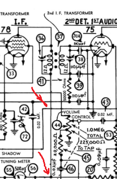
You could see the tiedot to B+ at the bottom (bottom red arrow) but not with the AVC (3rd intersect, top red arrow).
Also, for this error, if it exists in some form, to take effect, it needs to be on tthe sch which Dconant uses and he had to then modify the circuitry according to it, which he did not indicate he had done.
People who do not drink, do not smoke, do not eat red meat will one day feel really stupid lying there and dying from nothing.
Posts: 553
Threads: 89
Joined: Jun 2022
City: Marion
State, Province, Country: NY
I did not make a modification there.
Users browsing this thread: 1 Guest(s)
|
|
Recent Posts
|
|
Philco P45-6365 Universal Transformer Instruction Manual
|
| Can anyone guide me to where this may be found?GRG — 03:00 PM |
|
54C Complete Teardown/Rebuild
|
| I don't think that I have encountered a 12Z3 before, curious how it uses one of those but includes a #43, which is a 25 ...Arran — 02:17 PM |
|
HiFi (Chifi) tube amp build - but my own design.
|
| It's the other forum. I'm also in DIY, but mostly read there. Honestly, I kinda jumped into this without much thought to...TV MAN — 10:43 AM |
|
Philco 71 Code 125
|
| Hello,
I am in need of a schematic for this radio. Mine has the three separate circular tube shields and a shadow me...dconant — 08:06 AM |
|
Stromberg Carlson 1500 Squeal
|
| And life just keeps getting more complicated.dconant — 07:57 AM |
|
54C Complete Teardown/Rebuild
|
| Hello Roy,
here is this one
sincerely Richardradiorich — 12:45 AM |
|
54C Complete Teardown/Rebuild
|
| Richard,
Had grabbed it already but thank you just the same. I find myself wanting to find some way to block out the...glyphmon — 12:03 AM |
|
54C Complete Teardown/Rebuild
|
| Hello roy,
here is a link to the schematic .
Sincerely Richardradiorich — 11:54 PM |
|
54C Complete Teardown/Rebuild
|
| Richard,
The Silvertone 2014 also is a transformerless set, so I am incorporating a 1:1 600 ohm audio isolation transfo...glyphmon — 11:37 PM |
|
Preliminary work on wife's Silvertone 2014
|
| Did an alignment today which was interesting. IF alignment went great, almost all was already spot-on. Adjusting on th...glyphmon — 11:35 PM |
|
Who's Online
|
There are currently 2681 online users. [Complete List]
» 2 Member(s) | 2679 Guest(s)
|
|
|

|
 
|








