38-7 Chairside - What Is This?
Posts: 6
Threads: 1
Joined: Jan 2026
City: Vinton
State, Province, Country: Iowa
Posts: 5,652
Threads: 56
Joined: Sep 2008
City: Sandwick, BC, CA
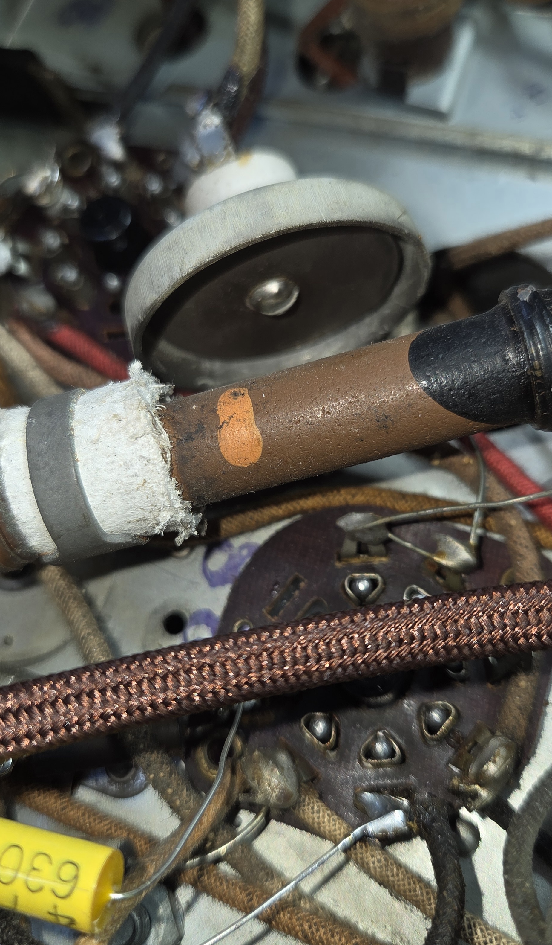
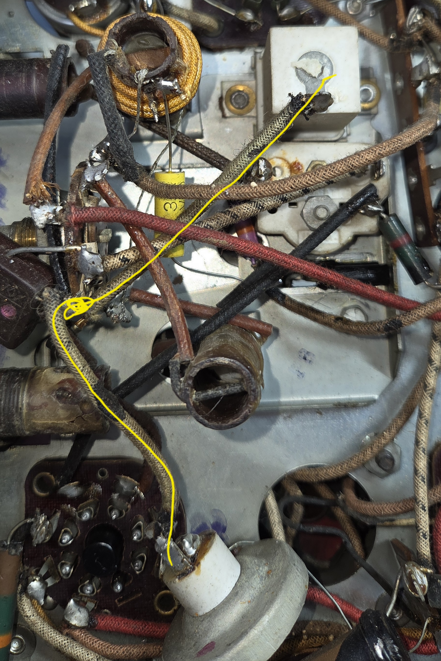
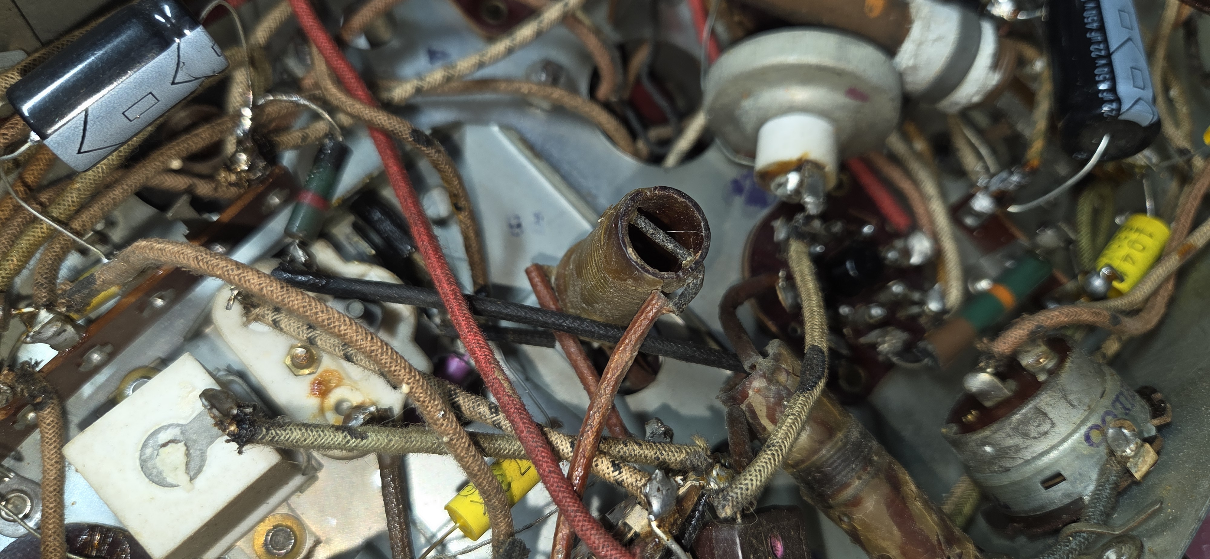
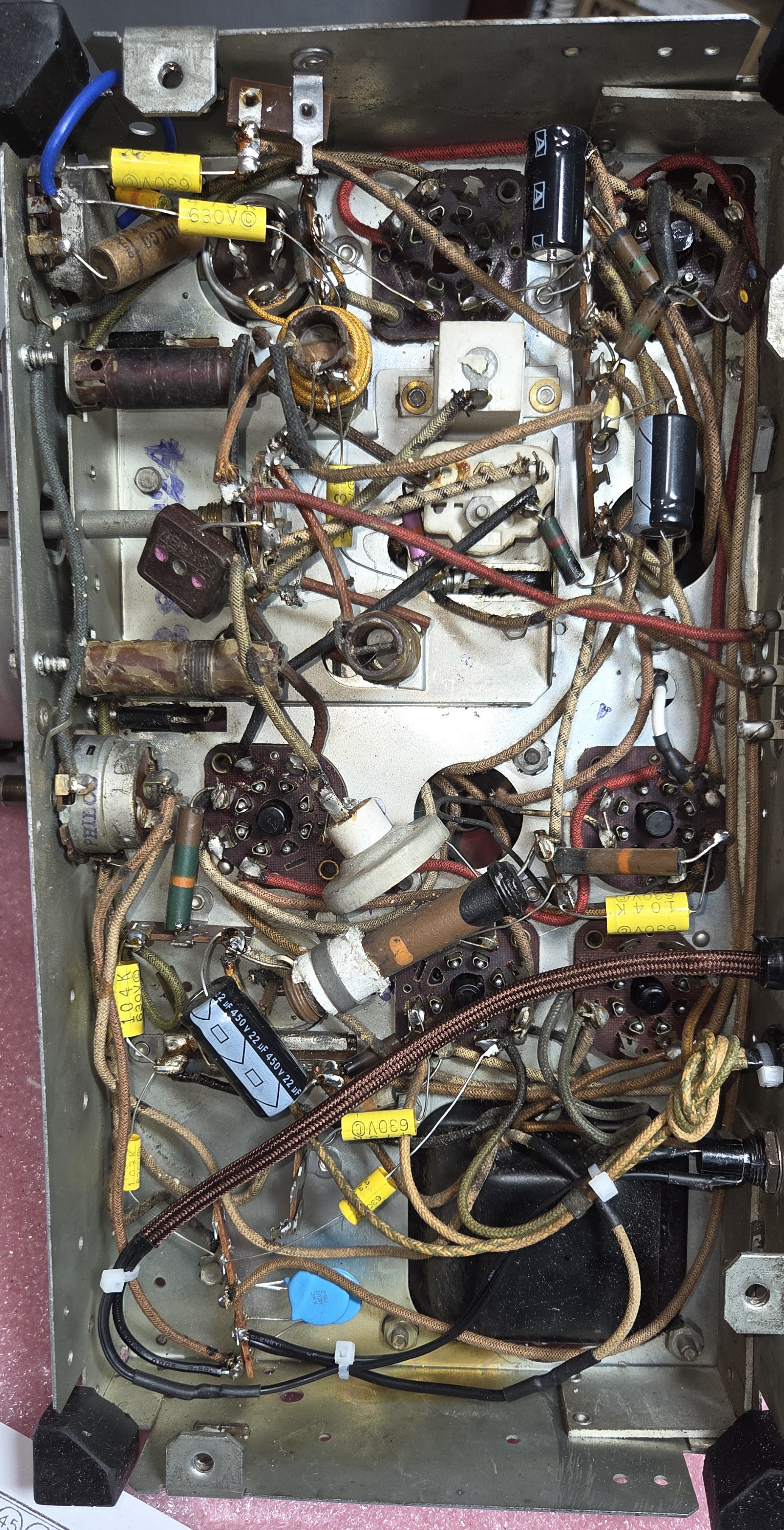
This is a good question, to me it looks a bit like a doorknob capacitor, but with terminals for soldering. However it has a metal case, that you say is grounded? An RF choke of some sort? That cloth covered wire winding around the outside of one of the coils has me curious too. It has the hallmarks of being "Hammed". By the way the 1936 and newer Philco models had brown rubber power cords, even though the cloth one looks cooler.
Regards
Arran
Posts: 212
Threads: 5
Joined: Sep 2005
City: Newark, Ohio
I think that is a thermal capacitor that is undocumented. Notice how close it is to resistor #12 , 10K 3 watt? As the resistor heats, the capacitance changes to prevent the oscillator from drifting.
Hope this helps.
Posts: 6
Threads: 1
Joined: Jan 2026
City: Vinton
State, Province, Country: Iowa
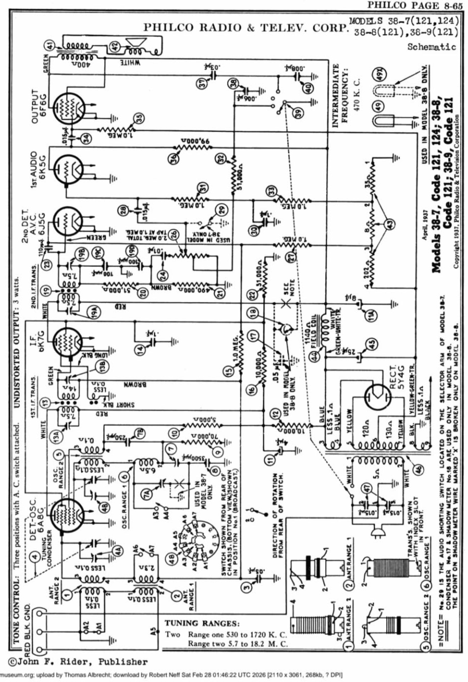
Ed, that would make sense. I'm thinking you are correct. I should have included the schematic ... which I'll do here. Do you see it in the schematic?
I'm thinking it's the dotted line ground symbol that says "used in Model 38-7 only". Though I still don't understand what it really does. When it gets warm enough, it grounds that line??
Aaron, I just replaced the 'ratty' rubber power cord with the new cloth covered one.
Posts: 431
Threads: 9
Joined: Apr 2023
City: Roanoke
State, Province, Country: Virginia
It is documented in the Philco service manual (38-7, codes 121 and 124, is on pp. 113-116).
Part 7A on the schematic is shown as a "Compensator Model 7 (1500 KC)," and is Philco part 31-6196. What you show in the photo, though, does not look like a compensator, which is a trimmer capacitor.
Dale H. Cook, GR/HP/Tek Collector, Roanoke/Lynchburg, VA
https://plymouthcolony.net/starcity/radios/
(This post was last modified: 03-10-2026, 12:43 PM by DaleHCook.)
Posts: 1,797
Threads: 55
Joined: Feb 2015
City: Roseville, MN
I think it's a compensator of sorts being that environment heat is slightly changing the capacitance, similar to a ceramic cap in an FM front end. Probably an experiment on Philco's part to see if the buying public understood what they did. On a hot summer Saturday afternoon you don't want the radio drifting when the Babe is at bat.
Posts: 212
Threads: 5
Joined: Sep 2005
City: Newark, Ohio
It is further explained in "Changes in Models" #280 .
Posts: 431
Threads: 9
Joined: Apr 2023
City: Roanoke
State, Province, Country: Virginia
Ed Locker Wrote: It is further explained in "Changes in Models" #280.
Ed Locker hit the nail on the head. What he found is the 38-7 121, 124 Run 3 and Run 4 sections on page 2 of Philco 1938 Changes in Models (Changes No. 6). They describe the thermal compensators. Although that section applies to Service Bulletin No. 280, the thermal compensators are not described in the bulletin, just in the changes.
Dale H. Cook, GR/HP/Tek Collector, Roanoke/Lynchburg, VA
https://plymouthcolony.net/starcity/radios/
(This post was last modified: 03-10-2026, 04:34 PM by DaleHCook.)
Posts: 18,427
Threads: 622
Joined: Oct 2011
City: Jackson
State, Province, Country: NJ
So it was your post on FB yesterday? See? Here it is that much better.
Someone even suggested a bias battery.
Transformer radios do not need them - they can generate their own negative bias. It is mostly used in AC/DC sets.
People who do not drink, do not smoke, do not eat red meat will one day feel really stupid lying there and dying from nothing.
Posts: 18,427
Threads: 622
Joined: Oct 2011
City: Jackson
State, Province, Country: NJ
OK, this is the description of it.
https://antiqueradios.com/forums/viewtopic.php?t=244627
Look at the post #10.
They replaced an existing compensator 7A they used up 'till Run 3, with P/N 31-6206 (a comp. cap).
Then the took a thermal compensator and soldered it IN PARALLEL to 7A compensator.
This is what you should have, yours is likely the Run #3.
Then in the next Rub #4 the took out the thermal compensator and replaced it with two caps P/N 30-1097.
People who do not drink, do not smoke, do not eat red meat will one day feel really stupid lying there and dying from nothing.
Posts: 6
Threads: 1
Joined: Jan 2026
City: Vinton
State, Province, Country: Iowa
Thanks to all for helping teach this old dog a new trick !
And Morzh, I'm not as savy to forums as you are. I felt that posting to two different threads would be a good idea. I've deleted my latest post on this subject, on this site, in another Philco 38-7 thread.
As for posting here and on Facebook, if I correctly understand your reply about my same post on FB, I see no issue with posting in two places. Just because someone is in a FB 'Radio group', that doesn't mean they're also on this site. So I'm going for the most exposure to all radio restorers to find answers.
If I misunderstood that part of your post, I apologize.
(This post was last modified: 03-11-2026, 12:14 AM by RFtech53.)
Posts: 5,652
Threads: 56
Joined: Sep 2008
City: Sandwick, BC, CA
The square ceramic object is most likely a padder condenser, which is for the tracking on the lower end of the dial, in some sets they call it a "600 padder". This temperature compensating device is certainly an oddity, I have run into zero temperature co-efficient caps in some Rogers built sets, but not one that intentionally varies with temperature, not in an 89 year old radio. I would guess that Philco must have have produced them in house as I can't recall seeing them in anything else, on first glance I thought maybe someone was playing around in there, I've seen chokes and other things added before to try and quash some interference, or sub another defective part. Someone was doing that with the antenna coil, either the primary is open or someone was experimenting with it in some way.
Regards
Arran
Posts: 6
Threads: 1
Joined: Jan 2026
City: Vinton
State, Province, Country: Iowa
The antenna coil ... could a tube have shorted and pulled enough current through the coil to fry it a few turns from the end?
I recently restored a 1938 Motorola 9A Ch=9-3 Chairside and it had the first IF coil partially re-wound. I was told by someone who restores a lot of 30's radios that it's a fairly common issue when a tube shorts in the first or second stage.
Posts: 5,652
Threads: 56
Joined: Sep 2008
City: Sandwick, BC, CA
Lightning could have been the culprit, if it looks burned, or some form of mechanical damage to the winding. The tubes themselves seldom short, and the shorts are usually between one grid, and another, or between the heater and cathode. What can cause an IF winding to fail might be the IF amplifier tube being biased improperly drawing excessive current through the primary, possibly due to a leaky capacitor, which is usually connected between the B+ and the plate of the IF amplifier tube. Sometimes they fail for mechanical reasons, like the wire physically breaks, or corrodes.
Regards
Arran
Posts: 18,427
Threads: 622
Joined: Oct 2011
City: Jackson
State, Province, Country: NJ
RFtech,
No, no issue with posting on Facebook; I post there too. It's just the experts on Philco are here. And if you need good expertise on just any radios, Antiqueradios.com. even though it is kinda competitor place, are also very good, plus the sheer number of people there is helpful.
The post I pasted here is from there.
But as for posting in several threads, it would be better if you gave a link to it, or even copypasted the post from it here, but sticking to one thread per one radio makes it more readable and clear to those who will open it in the future. I myself am not sure I'd understand why all of a sudden a post about the thermal compensator appeared in that other thread.
Mike.
People who do not drink, do not smoke, do not eat red meat will one day feel really stupid lying there and dying from nothing.
Users browsing this thread: 1 Guest(s)
|
|
Recent Posts
|
|
Philco P45-6365 Universal Transformer Instruction Manual
|
| Can anyone guide me to where this may be found?GRG — 03:00 PM |
|
54C Complete Teardown/Rebuild
|
| I don't think that I have encountered a 12Z3 before, curious how it uses one of those but includes a #43, which is a 25 ...Arran — 02:17 PM |
|
HiFi (Chifi) tube amp build - but my own design.
|
| It's the other forum. I'm also in DIY, but mostly read there. Honestly, I kinda jumped into this without much thought to...TV MAN — 10:43 AM |
|
Philco 71 Code 125
|
| Hello,
I am in need of a schematic for this radio. Mine has the three separate circular tube shields and a shadow me...dconant — 08:06 AM |
|
Stromberg Carlson 1500 Squeal
|
| And life just keeps getting more complicated.dconant — 07:57 AM |
|
54C Complete Teardown/Rebuild
|
| Hello Roy,
here is this one
sincerely Richardradiorich — 12:45 AM |
|
54C Complete Teardown/Rebuild
|
| Richard,
Had grabbed it already but thank you just the same. I find myself wanting to find some way to block out the...glyphmon — 12:03 AM |
|
54C Complete Teardown/Rebuild
|
| Hello roy,
here is a link to the schematic .
Sincerely Richardradiorich — 11:54 PM |
|
54C Complete Teardown/Rebuild
|
| Richard,
The Silvertone 2014 also is a transformerless set, so I am incorporating a 1:1 600 ohm audio isolation transfo...glyphmon — 11:37 PM |
|
Preliminary work on wife's Silvertone 2014
|
| Did an alignment today which was interesting. IF alignment went great, almost all was already spot-on. Adjusting on th...glyphmon — 11:35 PM |
|
Who's Online
|
| There are currently no members online. |

|
 
|