Beginning a 37-620 Restoration
Posts: 3,186
Threads: 226
Joined: May 2008
City: Omak
State, Province, Country: WA
Hello Roy,
Really cool dim bulb tester I am getting ready to build a new one too.
maybe I can scronge up old stuff too.
Sincerely Richard
Posts: 1,135
Threads: 54
Joined: Feb 2013
City: Shenandoah,
State, Province, Country: Pennsylvania
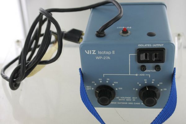
Hi Roy, most variacs are auto transformers so you still need an isolation transformer. The picture I posted is what I have been using for over 40 years. Isotap isolation transformer. You can vary the output in 5V increments from 25V to 150V AND it is an isolation transformer in one neat small unit, saving bench space and less expensive than separate variac and isolation transformer. I believe they are still sold by some companies or they show up on eBay!
Ron
Bendix 0626. RCA T64 Philco 20B
Philco 41-250. Philco49-500
GE 201. Philco 39-25
Motorola 61X13. Philco 46-420 Crosley 52TQ
Philco 37-116. Philco 70
AK 35 Philco 46-350
Philco 620B. Zenith Transoceanic B-600
Philco 60B. Majestic 50
Philco 52-944. AK 84
Posts: 18,427
Threads: 622
Joined: Oct 2011
City: Jackson
State, Province, Country: NJ
Roy
What makes a good Variac...
Well, my opinion: it should handle any radio that you restore without overloading itself. The output V-rangle of 0-150VAC is sufficient.
I have a 500 VA (read- Watts, though VA and a Watt is not exactly the same) Variac.
There is no consumer radio that this is not sufficient for.
And it is rather small.
(I also have a second one, 3kVA, up to 220V in and about 300V out. Used it once. But not too much money, so a good thing to have just in case. Don't think you need it at this point.)
An isolation transformer. Mine is 250W or so. Again, sufficient for most or all radios. Mine is a hospital grade Fluke, bought cheaply on eBay used equipment sale.
Now, about Variacs with isolation inside: due to size being an issue, the output transformer might be undersized, so you have see if the ratings are what you need. They might be sufficient for some (or even most) jobs but could be under-powered for some others.
I prefer things separate.
People who do not drink, do not smoke, do not eat red meat will one day feel really stupid lying there and dying from nothing.
Posts: 1,797
Threads: 55
Joined: Feb 2015
City: Roseville, MN
MrFixr,
Re: tone control.
Your mod would work fine if the chassis were wired as the schematic shows. In our case the 4 position tone switch has been replaced with a 5k pot/capacitor tone control. So, the question is since the 4 position switch is not at hand, can the existing pot/capacitor continue to be used or can some other circuit be used. If some other circuit is implemented what parts are needed? Also remember that the current switch on the pot is the power switch.
Posts: 109
Threads: 15
Joined: Mar 2024
City: BERTHOUD
State, Province, Country: CO
Roy,
Regarding your questions on measuring B+, one document that I think does a great job of explaining all this is the Philco Trouble Shooting Techniques handbook. This is a short 11 page doc but it does an amazingly good job of giving an overview of a process you can follow.
If you want to go deeper, in my humble opinion, the book that is the best is Elements of Radio Servicing, Marcus and Levy. I still have my copy I got while in the navy in 1981. You can’t go wrong with that book, if you want to dig deeper. The third edition is the best if you can find a used one.
Another good reference is Radio Troubleshooters Handbook, Alfred Girardi. The cool thing in this book is they have this case-study massive section that lists every radio made in the 30s-40s, and they list common defects and problems and solutions. That has come in handy for me many times over the years.
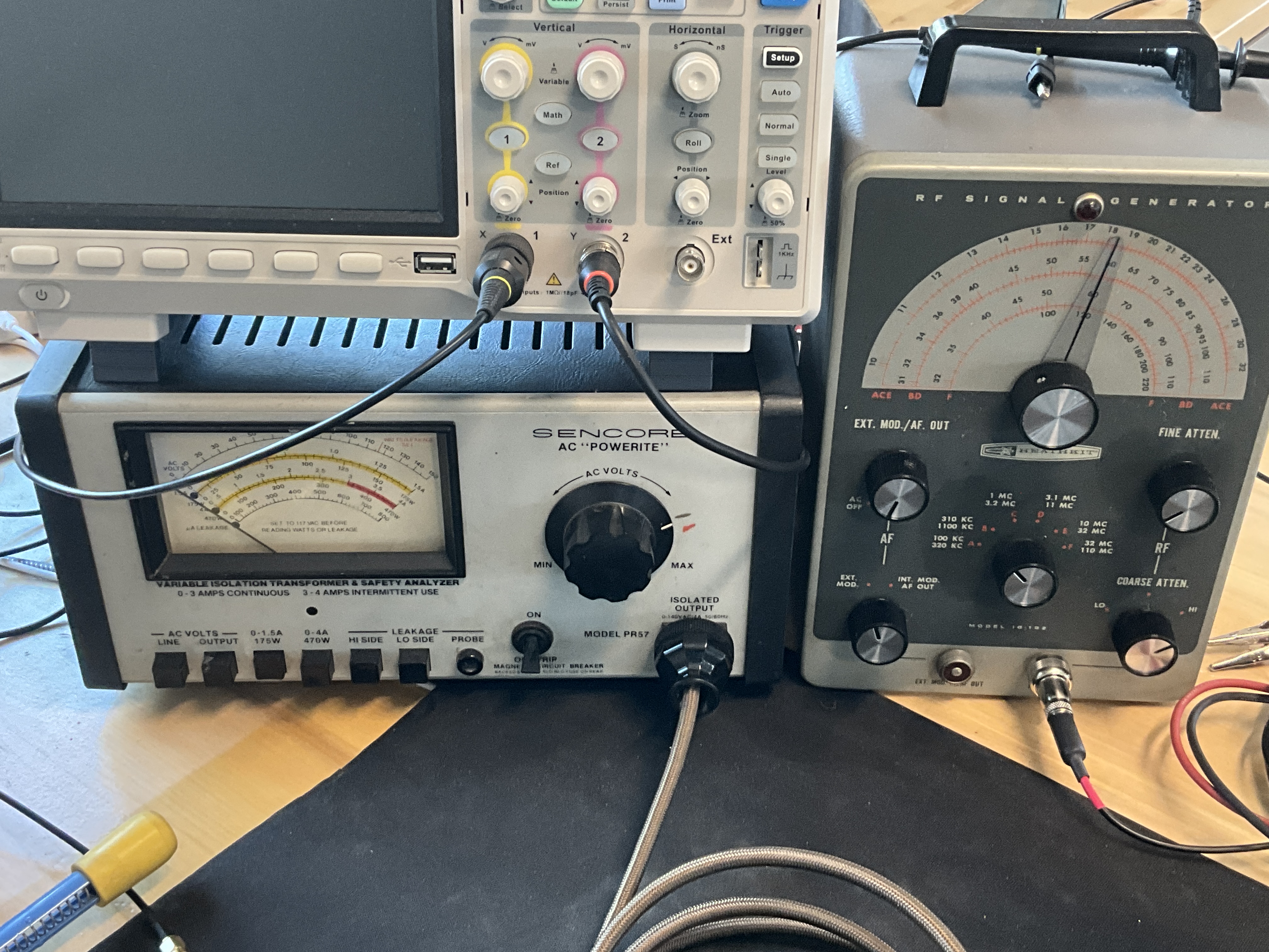
For Signal Generator, you really just need one for alignment. My personal favorite is the Heathkit IG-102. It was made in the early 60s I believe. And because it was a Heathkit it is easy to service and find documents for. And really it is so simple to use and to understand. You can find used ones on eBay quite often. There a couple guys who service and calibrate and resell them.
For isolation transformer, my favorite is the Sencore PR57. It isn’t cheap when you can find a used one, but I had a bunch of them when I owned an electronics repair shop in San Diego back in the 80s and you can’t go wrong. But not the cheapest solution.
These are just my thoughts from someone out here messing around and trying to restore a few of these beauties. Hope this helps some. George
Craftsmanship is an ongoing cycle of learning fueled by patience, persistence, and care, where every project refines our judgment and challenges our skills, in the steady pursuit of the Path to Mastery.
(This post was last modified: 04-12-2026, 06:41 PM by SRv2.)
Posts: 18,427
Threads: 622
Joined: Oct 2011
City: Jackson
State, Province, Country: NJ
The scope is an HP 
People who do not drink, do not smoke, do not eat red meat will one day feel really stupid lying there and dying from nothing.
Posts: 172
Threads: 10
Joined: Mar 2026
City: Franklin
State, Province, Country: Maine
Thank you all for your input.
Mike, I too am a person who likes things separate (I still keep my music in an MP3 player plugged into my car's USB port, and take photos with a standalone camera, for example) but I think for this stage of the game for me, since 462ron has had good luck with his Viz WP-27A, I might look into that route. Down the road if things get serious, I'll refer back to this thread to check on upgrades.
As for the WP-27A, I see one on eBay listed as parts/not working by virtue of the seller being unable to test it, and I also see a tested and working one, but it appears to be the older RCA-branded version. Of course, any piece of equipment can fail, but would people shy away from a working unit just for it's age, or are these pretty resilient over time?
George, thanks for the links and resource recommendations. I will do some digging for sure. I see some IG-102s on eBay for reasonable money as well, so I'll try to snag one. I see there are also re-cap kits for sale so I presume these get rebuilt with some regularity. Most of the ones that I see listed don't show any kind of test lead. I presume that's something that I'd have to pick up separately or fabricate myself?
Thanks again, all.
Best wishes,
Roy
Posts: 109
Threads: 15
Joined: Mar 2024
City: BERTHOUD
State, Province, Country: CO
Roy,
There is a guy on eBay that sells lead sets that will work on the signal generator. You can make your own but his costs are so reasonable I went that route. You have to specify the connector type. If original connector on the IG-102, it is the switchcraft connector. He has one with capacitive coupling built in and one with RMA dummy antenna. Just one option to consider. Here are a couple links to review. Other folks here with more experience than me may have better recommendations.
https://ebay.us/m/Kv0W3k
https://ebay.us/m/8Af2LB
Hope this helps some. Also, I have had pretty good luck with test equipment off eBay. I know some folks don’t like eBay and I understand the pros/cons. But it’s an option. George
Craftsmanship is an ongoing cycle of learning fueled by patience, persistence, and care, where every project refines our judgment and challenges our skills, in the steady pursuit of the Path to Mastery.
Posts: 172
Threads: 10
Joined: Mar 2026
City: Franklin
State, Province, Country: Maine
George, thanks again. Another newbie question on the test lead - what's the use case for the one with the .022uF capacitor built in vs the one with the RMA dummy antenna?
From the test procedure for the 37-620, I know it says to connect the signal generator to the control grid of the 6A8G (for IF alignment) or terminal 1 on the aerial input panel (for RF alignment) through a .1 uF capacitor. Is that still the case with either of these leads? .022 uF is a far cry from .1uF, but not sure if that was the manufacturer covering their butt back in the day.
Best wishes,
Roy
Posts: 3,186
Threads: 226
Joined: May 2008
City: Omak
State, Province, Country: WA
hello Roy,
I have one of those RCA-branded version Isolation trans. Since my repairshop was RCA Dealer but the main unit I use is my Sencore Prorite like George has in his photo .
Sincerely Richard
Posts: 1,135
Threads: 54
Joined: Feb 2013
City: Shenandoah,
State, Province, Country: Pennsylvania
Roy, that Viz or RCA IsoTap is good for 400W, back in the 70s I did TV repair and used it!
Ron
Bendix 0626. RCA T64 Philco 20B
Philco 41-250. Philco49-500
GE 201. Philco 39-25
Motorola 61X13. Philco 46-420 Crosley 52TQ
Philco 37-116. Philco 70
AK 35 Philco 46-350
Philco 620B. Zenith Transoceanic B-600
Philco 60B. Majestic 50
Philco 52-944. AK 84
Posts: 18,427
Threads: 622
Joined: Oct 2011
City: Jackson
State, Province, Country: NJ
Roy
Absolutely, if it is a good transformer, use it.
The main criteria are like this:
1. It is enough (V/I/W) for your current project(s)
2. There is enough space to use it.
3. It is affordable.
After this, it all is personal choice and matters of taste.
People who do not drink, do not smoke, do not eat red meat will one day feel really stupid lying there and dying from nothing.
Posts: 2,327
Threads: 23
Joined: Jul 2020
City: Greenlawn
State, Province, Country: NY
Hi RodB,
Seems that the control should be swapped out. A 5K pot is not appropriate for use as a tone control in a high impedance tube circuit. you would be better off with a 500K or higher pot, preferably a 1 megohm audio taper pot. Any pot and switch combo of this spec would work.
It is possible that the control currently in this set was used as a volume control in an older non-AVC TRF set where the wiper was grounded and the control shunted the antenna input and increased cathode resistance on the 1st RF amp tube (a common way to control volume in Depression era TRF sets), and as another member (Sorry, I can't remember who) stated, this was probably put in for the power switch function and the pot was not used.
"Do Justly, love Mercy and walk humbly with your God"- Micah 6:8
"Let us begin to do good"- St. Francis
Best Regards,
MrFixr55
Posts: 1,797
Threads: 55
Joined: Feb 2015
City: Roseville, MN
MrFixr, I totally agree on the tone control. One to two meg is my experience. When I first saw what he measured at 5k I had to read that again just to make sure I read correctly. As I see the situation, he can temporarily put in a high voltage 0.022mfd cap on the plate just to improve the bass a little, look for a tone pot w/switch to replace the current one, then wire in the simple capacitor/pot, in either the output stage plate or the grid circuit, when it arrives. I really like the pot that can be set to your preference. I'm even considering changing mine, I'm pretty sure I already have the control w/switch.
Posts: 172
Threads: 10
Joined: Mar 2026
City: Franklin
State, Province, Country: Maine
An update.
Today, using my new-old RCA Isotap II WP-27A, I did bring the chassis gradually up to full power. To my great relief, all of the magic smoke stayed inside and I was able to get a couple signals.
While I know it is a poor setup, at the moment, I have a long wire coiled into a ball. This is something that I do intend to get mounted to the side of the building (insulated on both ends, as I've seen). For testing purposes, I also have a AM transmitter in my office where I'm working on this radio, and a Bluetooth receiver plugged into that. I was successfully able to stream from a laptop to the Bluetooth receiver, and have the receiver's audio sent out on AM - approximately 1630 kHz - and the radio picked it up and did a reasonable job playing it. I was also able (especially when making physical contact with my antenna ball) to receive - though not great - a local radio station about 10 or 12 miles away. A very faint more distant station came in as well. The lower shortwave bands were completely silent for me, but I did pick up a couple faint stations on the upper shortwave bands, including one that sounded like it was in Spanish.
So, I feel reasonably good about the fact that it is both receiving and making sounds. I feel very good that nothing seems to be burning up either.
I think my next stage will be to do the alignment on it to the best of my abilities. I also got my new-old IG-102 signal generator. I need to order a lead for it, and I am also waiting for the capacitor to come in to put inline with the connection. From a number of the videos I've seen, though many radios do work after recapping, the alignments seem to make a big improvement. Since I changed all the caps and resistors, I'm sure there's some adjusting that could help.
Once I've done the alignment, I may follow up with some additional questions if I still think there's improvement to be gained in the output, which there probably will be.
Thanks again to everyone who contributed to me not completely botching this chassis so far.
A video of the first song I streamed to it is available here (Mike, don't watch, there's a dim bulb tester in here you don't want to see).
https://youtu.be/tmjOuJ0Lx7M
If you can't hear the music, it's because of copyright.  Maybe next time I'll try classical music.
Best wishes,
Roy
Users browsing this thread: 2 Guest(s)
|
|
Recent Posts
|
|
Philco P45-6365 Universal Transformer Instruction Manual
|
| Can anyone guide me to where this may be found?GRG — 03:00 PM |
|
54C Complete Teardown/Rebuild
|
| I don't think that I have encountered a 12Z3 before, curious how it uses one of those but includes a #43, which is a 25 ...Arran — 02:17 PM |
|
HiFi (Chifi) tube amp build - but my own design.
|
| It's the other forum. I'm also in DIY, but mostly read there. Honestly, I kinda jumped into this without much thought to...TV MAN — 10:43 AM |
|
Philco 71 Code 125
|
| Hello,
I am in need of a schematic for this radio. Mine has the three separate circular tube shields and a shadow me...dconant — 08:06 AM |
|
Stromberg Carlson 1500 Squeal
|
| And life just keeps getting more complicated.dconant — 07:57 AM |
|
54C Complete Teardown/Rebuild
|
| Hello Roy,
here is this one
sincerely Richardradiorich — 12:45 AM |
|
54C Complete Teardown/Rebuild
|
| Richard,
Had grabbed it already but thank you just the same. I find myself wanting to find some way to block out the...glyphmon — 12:03 AM |
|
54C Complete Teardown/Rebuild
|
| Hello roy,
here is a link to the schematic .
Sincerely Richardradiorich — 11:54 PM |
|
54C Complete Teardown/Rebuild
|
| Richard,
The Silvertone 2014 also is a transformerless set, so I am incorporating a 1:1 600 ohm audio isolation transfo...glyphmon — 11:37 PM |
|
Preliminary work on wife's Silvertone 2014
|
| Did an alignment today which was interesting. IF alignment went great, almost all was already spot-on. Adjusting on th...glyphmon — 11:35 PM |
|
Who's Online
|
There are currently 1842 online users. [Complete List]
» 2 Member(s) | 1840 Guest(s)
|
|
|

|
 
|