Farm Model - Battery Eliminator?
Posts: 5,652
Threads: 56
Joined: Sep 2008
City: Sandwick, BC, CA
Here is the page with the unit Rob posted the schematic for: https://www.solorb.com/elect/hamcirc/far...index.html It looks like it's mounted inside a generic double gang device box, I'm not sure how I feel about mounting a transformer to perf board mounted upside down, though it does look like the iron of the transformer has bolt holes if needed. The set it's installed in is typical of some of those 1.4 volt + 90 volt battery sets, the cabinet has lots of space to accommodate battery storage. Canadian battery sets are similar, except that there was apparently a market for them right into the late 1950s before transistor sets took over. One thing that many Canadian sets have is a fifth tube, either an RF amplifier, or an extra IF amplifier tube, so they usually make good DX machines once you get them working right. A lot of the pre war models, with the 2 volt tubes, have push-pull outputs, and even shortwave bands, the ones that didn't used a #33 pentode, which still makes plenty of volume.
The "wall warts" I'm familiar with are linear with a mains transformer, and those are no problem at all other then the primary usually has a built in fuse. I've never tried a switcher style one to power a tube radio, which I think may have a "buck convertor" inside, the really crude ones use a capacitive dropper.
Regards
Arran
(This post was last modified: 04-26-2026, 03:32 PM by Arran.)
Posts: 2,327
Threads: 23
Joined: Jul 2020
City: Greenlawn
State, Province, Country: NY
Hi SRv2,
Please list the makes and models of the farm sets. We are happy to help, as farm sets were extremely regionalized in response to what power was available on the farm. That varied by location. 6V or 32V windmills and storage batteries were popular in some areas, 32V generators with storage batteries in other areas, and in yet other areas, the radios ran off batteries. Some 6V sets had the same tube compliment as a nice car radio or some home radios and were excellent performers. The 1.5V / 90V sets performed like the 4 tube or 5 tube (RF amp before the convertor) battery portables that they were based on with good signal sensitivity but very weak (0.005W to 0.2W) output power.
There were power supplies that were sold by some companies or even the manufacturers themselves to replace the batteries in the 1.5V / 90V sets when rural electrification projects like the TVA finally brought power to the farms. One popular one was the Silvertone "Power Shiftr" for 1.5V / 90V radios. (I have 2 of them). RCA built them also and some sets were drilled for the chassis and power switch for these convertors. I don't believe that there were power supplies built for the 2V / 90V, 2V / 135V 6V or 32V radios. Often, in celebration of electrification, Radio stores would hold trade - in sales where people traded in their battery sets for utility powered sets, sometimes with sponsorship from the utilities, then would hold a public bonfire where the old battery sets were burned. Zenith made at least one 6V set that was switchable between 6V and 117V.
I too developed a bit of an eBay addiction for a while. I was always interested in antique radios; I trained myself in electronics as a kid. My hobbies of electricity, electronics, mechanics and plumbing, coupled with my education as a clinical lab technologist segued into a rather successful career as a clinical engineer for a biomedical manufacturer. Some of what I bought was in homage to "the ones that got away" like my Grandma's Radiola 17 that was promised to me but taken by someone else when she sold the house. Then there were others that interested me. I now have more than 80 radios spanning the 106 year history of the broadcast industry, including a Westinghouse RC and Aeriola Sr, 2 of the first commercial broadcast receivers, ca 1921-1922, a FADA 160 and Radiola 2, ca 1923, a Radiola 3, Atwater Kent 10C, and 20, Ca 1924, and so on. I can't say how much I paid for some of the Holy Grail sets like that Radiola II, Wesringhouse RC and the A-K 10C because the statute of limitations has not run out with Ms. Fixr. The radios I have cover the development of the industry from these early regenerative and TRF sets to a Radiola 60, the first Superheterodyne that was actually designed for house current, an incomplete Radiola Superheterodyne AR812, a Philco Model 20, A GE version of the RCA R7A, and a slew of radios from the late 1930s, 1940s, 1950s, a few from the 60s, 70s and 80s. I also have a gaggle of tube HiFi equipment. All have either been brought back to working condition or restored by myself. About 1/4 are sets that I have owned since childhood, given to me by friends and neighbors or rescued from the curb or the town dump. 30 years ago, I found a Fisher 400C and Fisher 800C Stereo receivers at the curb. These things are worth several hundred apiece. Both work!
"Do Justly, love Mercy and walk humbly with your God"- Micah 6:8
"Let us begin to do good"- St. Francis
Best Regards,
MrFixr55
Posts: 5,652
Threads: 56
Joined: Sep 2008
City: Sandwick, BC, CA
Quote: " I don't believe that there were power supplies built for the 2V / 90V, 2V / 135V 6V or 32V radios" There was, there was another "Electro" model designed for the pre war 2 volt sets, and a Silvertone Power Shftr for the same, I've never seen the Electro one other then in old magazine ads, and the Silverone one is not very common, according to Radiotvphononut. One thing that could be done with the 2 volt sets was to operate the filaments with a wet cell, so I think that many were kept in service that way since all you had to do was tap off of one cell of a storage battery. My experience with farm sets is that many survived because they were put into closets, or basements, once the power lines came into an area. Also I've never heard of a "Trade in Event" where the battery radios were destroyed afterward, you have to remember that many of these sets were purchased through mail order catalogs, like Sears, Montgomery Ward, Eatons, Simpsons, or the Hudson's Bay Company, because the owners lived in remote or semi remote areas off the grid. I have seen the odd set that was electrified by converting the set to AC tubes, and several botched attempts at same. Most of the successful conversions were with outboard power supplies with sockets provided for the battery plugs, which is another strike against that BEAR power supply with the allegator clips.
Brand Z I think did offer AC and 6 volt sets, so did Sentinel, I'm sure others did as well since many manufacturers were based in the greater Chicago area. Those would have been the models that used AC tubes, so adding an extra primary for the vibrator would have been simple enough, not sure if they used a synchronous vibrator or a rectifier tube, in both modes, or in alternate modes, like the synchronous vibrator for 6 volt only. I only have one 32 volt radio, and it's a Phonola based off of a Wells Gardner design, the 6 volt Stewart Warner set I have uses 2 volt battery tubes in a series-parallel arrangement, and a synchronous vibrator.
Regards
Arran
Posts: 136
Threads: 38
Joined: May 2015
City: Brandon, SD
What voltages
(This post was last modified: 04-27-2026, 11:00 PM by sdradioman.)
Posts: 2,327
Threads: 23
Joined: Jul 2020
City: Greenlawn
State, Province, Country: NY
Hi Arran,
Unfortunately, I can't remember where I read the bonfire bit but I did read it and believed that it came from a reliable source.
I'm sure that you know this but for others following the thread, my RCA 6BT had the option to run off 6V as opposed to 2V / 135V. They had a synchronous vibrator power supply attachment that made the set a "2V / 4V" set where they would use 2V from one cell of the 6V battery for the heaters and 4V from the other 2 cells of the battery. This is because batteries of the era had the straps that connected the cells in series on the top of the battery outside of the case. The 6BT (tombstone) and 6BK (console) cabinets were very similar to other RCA models at the time. These sets were serious performers as they used Class B output stages and good size speakers, 8" for the tabletop and 12" for the console. both were dynamic speakers with substantial permanent magnets (possibly AlNiCo?). The interesting thing is that audio power output for the vibrator supply equipped sets was less than the output of the sets with B batteries. I found that to be interesting.
I, too, have never seen a 2V version of the "Power Shiftr" and don't know if the B voltage was selectable for 90V vs 135V. Seems that many of the Silvertone battery sets with 2V or even 4V filaments used 90V for B+. I suppose that setting the jumper for 6 tubes and replacing the rectifier with silicon diodes may boost the voltage to 2V. Tube current for sets with single end outputs should be similar to the 1.4V tubes. However, for me, this would not be useful until I get my Coranado 650 working, as the RCAs (5BT and 6BT) use 135V for B voltage and I have successfully built a power supply for them.
"Do Justly, love Mercy and walk humbly with your God"- Micah 6:8
"Let us begin to do good"- St. Francis
Best Regards,
MrFixr55
Posts: 1,797
Threads: 55
Joined: Feb 2015
City: Roseville, MN
There's an interesting circuit that's been around for awhile. It's a solid state field coil or filter choke. It's really a simple regulator that will handle up to 100ma, probably a little more if heat sinks are used. If you google "solid state filter choke" the link to Antique Wireless Association will be the one. I looked at using the LR8 several years ago for a 90 volt supply for farm radios but it only supplies 10ma when most farm radios need 30-50ma. Thisl one would handle it nicely and it's adjustable.
Anyone use this in the past?
Posts: 18,427
Threads: 622
Joined: Oct 2011
City: Jackson
State, Province, Country: NJ
Well, it is just a simple parametric regulator, standard circuit, but it will need a heat at any sensible current. A 50mA at 25V dropout (which is not even what it can be) will result in 1.25W and TO-220 will not like it without at least some sort of a heatsink.
At 100mA 2.5W will make it not touchable.
The R(theta-j)A is 62.5C/W. So 2.5W will raise the crystal temperature by 156 degrees C. At room temp it already is 31 degrees above the maximum allowed.
So I hope they have that thing mounted on a heatsink.
This said, yes, a regulator does a good job to eliminate ripple.
But. If they used a classic regulator (op-amp-based), they would achieve better cleaning. Like an LDO.
People who do not drink, do not smoke, do not eat red meat will one day feel really stupid lying there and dying from nothing.
Posts: 109
Threads: 15
Joined: Mar 2024
City: BERTHOUD
State, Province, Country: CO
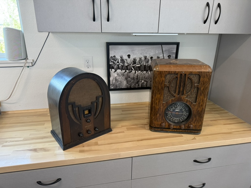
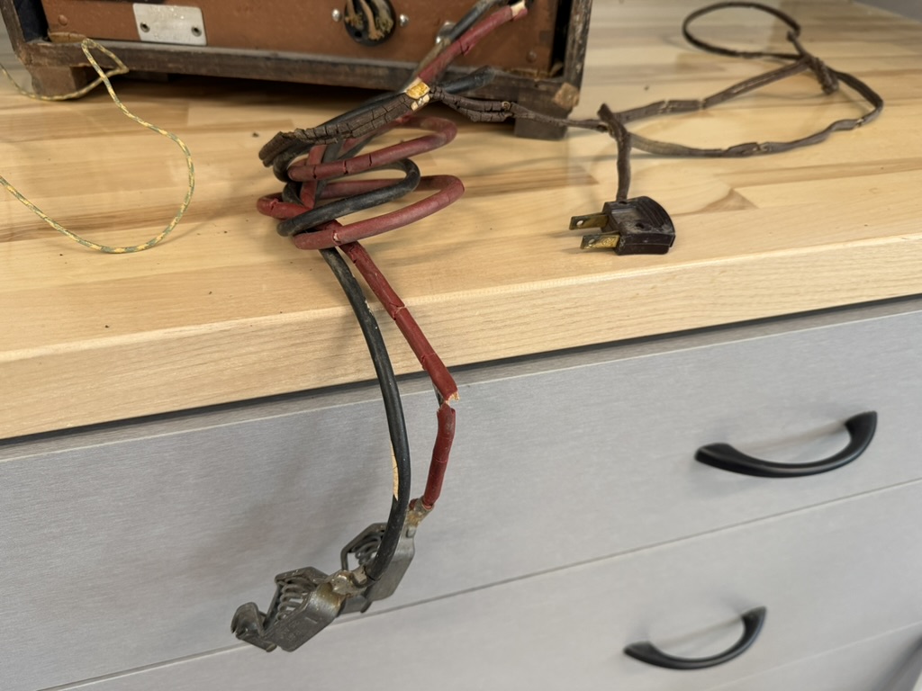
Hey all, I had a chance today to pull down the 2 farm units from my upper cabinet display today. Some good news, and some questions for the group. Here are the models I have and some details. Pics attached also for reference.
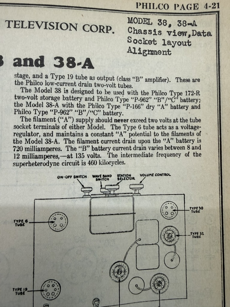
1. Philco model 38 - built 1934:
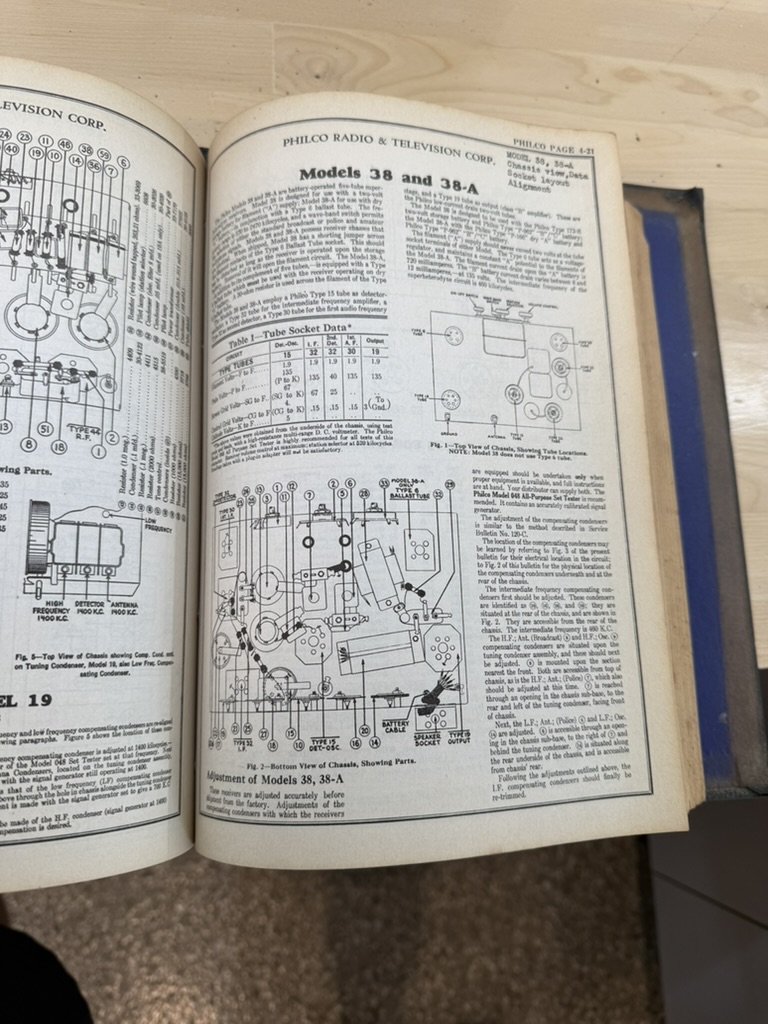
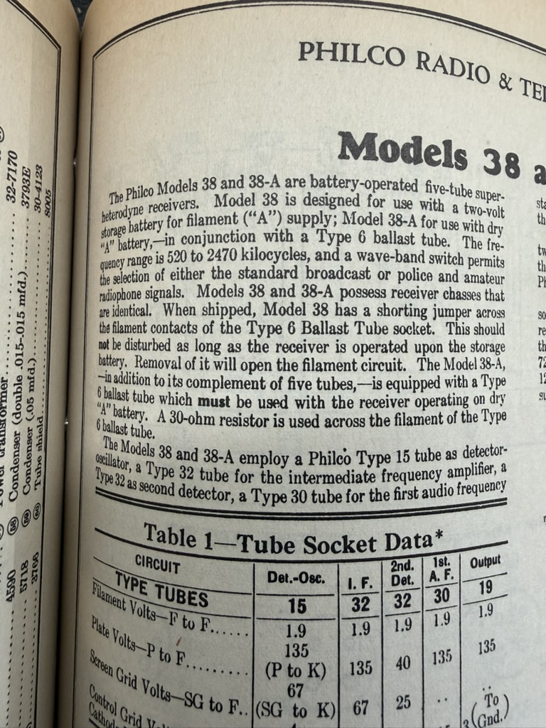
According to my Rider volume IV (the schematic on the Philco site was pretty hard to read, but I have all the Rider volumes which comes in handy now and then) - this unit needs;
a. A supply: 2V, type 172-R - I believe this type refers to the Philco 2 volt lead-acid battery from the 1930s
b. B supply: 90V, type P-962 - another Philco type reference for heavy-duty battery back
c. C supply: -4.5V? or -9V? is that correct?
options:
- doesn't look like Rod's schematic design will work for this model
- doesn't seem like the Powr Shiftr will work either since it is 1.2v filament and no C supply - is that correct?
- ARBE-III will work - is that correct?
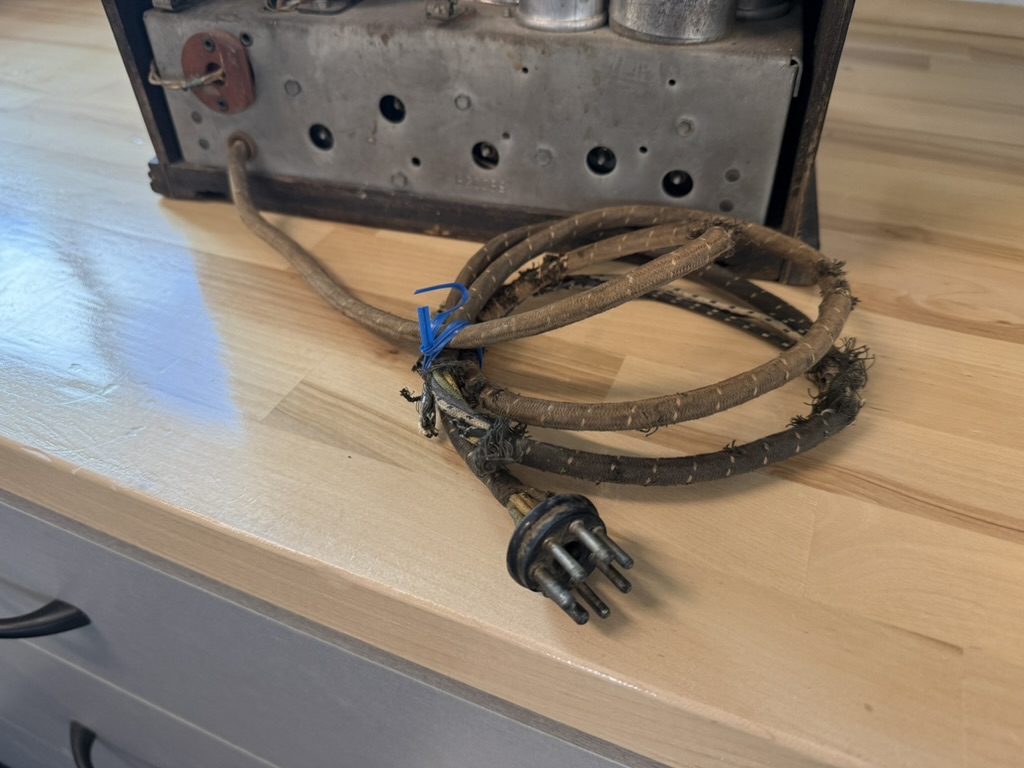
- one challenge will be hooking up the ARBE-III to the Philco 6-pin battery plug - is there a female plug end available somewhere that I could wire up to the ARBE-III, does anyone have a source for that?
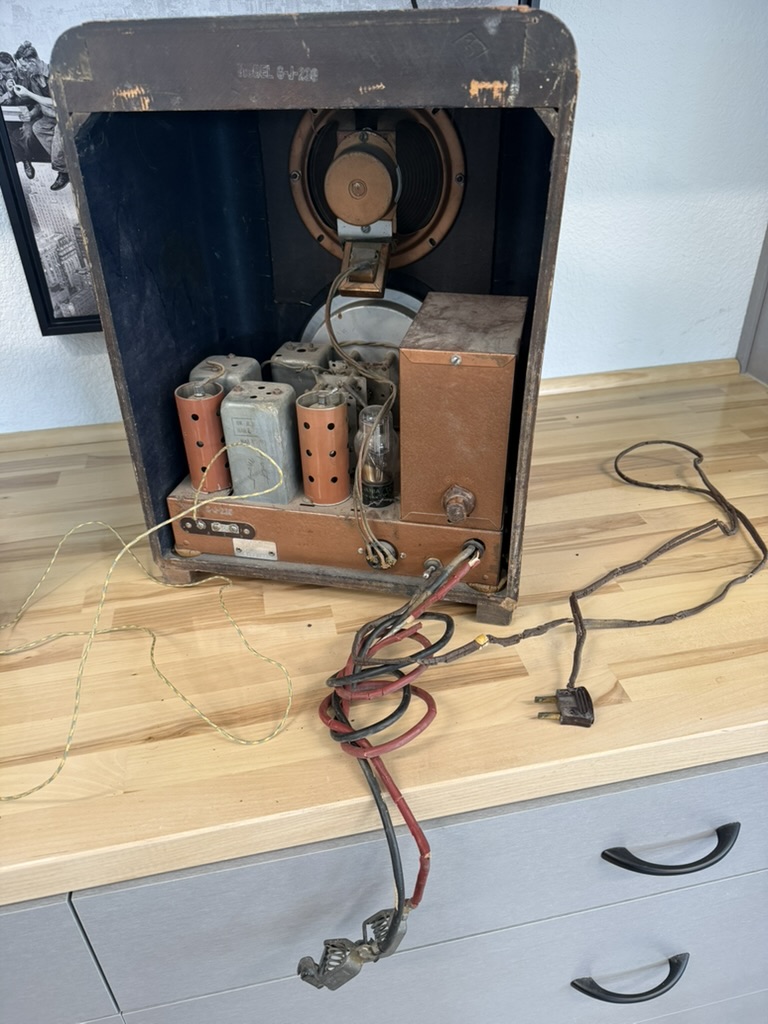
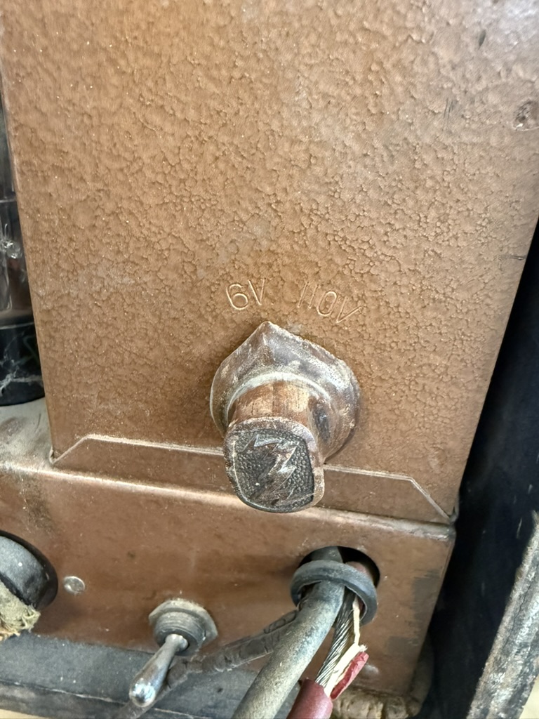
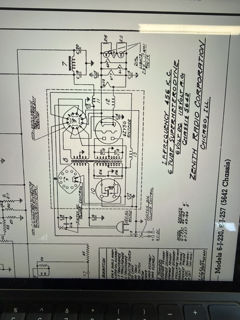
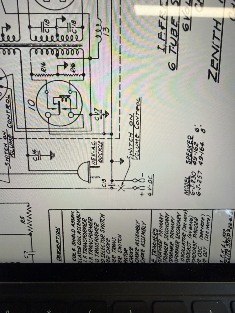
2. Zenith model 6-J-230, chassis 5646, built 1938:
Here I lucked out - this unit is a 110V AC -or- 6 VDC unit. When I was originally looking at it, I only saw the 6V battery connectors and I didn't see the AC cord stuffed in the unit. It has a switch on the back to toggle between 110V and 6V. So, I can work on this one in 110VAC mode. I do have a separate power supply that can delivery the 6VDC if I wanted to test this out once repaired. So I'm in the clear on this unit. Well, in the clear for how to power it, but dang this unit needs some TLC haha. Gonna need to psyche myself up for this renovation.
Pics attached for reference. I really, really appreciate the time and effort everyone here has put in to throw out input and feedback. Super helpful.
Oh, wait a second, I know the solution to both of these units - BONFIRE! 
Craftsmanship is an ongoing cycle of learning fueled by patience, persistence, and care, where every project refines our judgment and challenges our skills, in the steady pursuit of the Path to Mastery.
(This post was last modified: 04-27-2026, 08:20 PM by SRv2.)
Posts: 1,419
Threads: 41
Joined: Jan 2014
City: Wellborn Florida
Different battery chemistry will give you different voltages. Lead acid battery 2 volts per cell. David
Posts: 1,797
Threads: 55
Joined: Feb 2015
City: Roseville, MN
You can use the schematic I posted by adjusting the 1.4 volt supply to 2 volts and using three 1.5 volt cells for the C battery, it doesn't draw any current so,you can use button cells.
Posts: 109
Threads: 15
Joined: Mar 2024
City: BERTHOUD
State, Province, Country: CO
Rod,
Ok that makes sense. The 500k pot may have enough range to get the LM317 output to 2v, or I could increase the 220 ohm resistor up some. And the three batteries idea is good for C supply. I may go this route since I could build it relatively cheap and permanently install it in the radio, and just hard wire the 6 pin connector wiring onto the power supply. Ok that’s one option, thank you. George
Craftsmanship is an ongoing cycle of learning fueled by patience, persistence, and care, where every project refines our judgment and challenges our skills, in the steady pursuit of the Path to Mastery.
Posts: 18,427
Threads: 622
Joined: Oct 2011
City: Jackson
State, Province, Country: NJ
SRv2
1. It is NOT 500K. It is 500 Ohm.
2. You actually might want a lower pot value as the output is proportional to that resistor in the ADJ pin to GND path. So if you have 220 Ohm pot, you will have the range from 2.5V and down. Accurately trimmed. Though 500 will work also.
People who do not drink, do not smoke, do not eat red meat will one day feel really stupid lying there and dying from nothing.
Posts: 109
Threads: 15
Joined: Mar 2024
City: BERTHOUD
State, Province, Country: CO
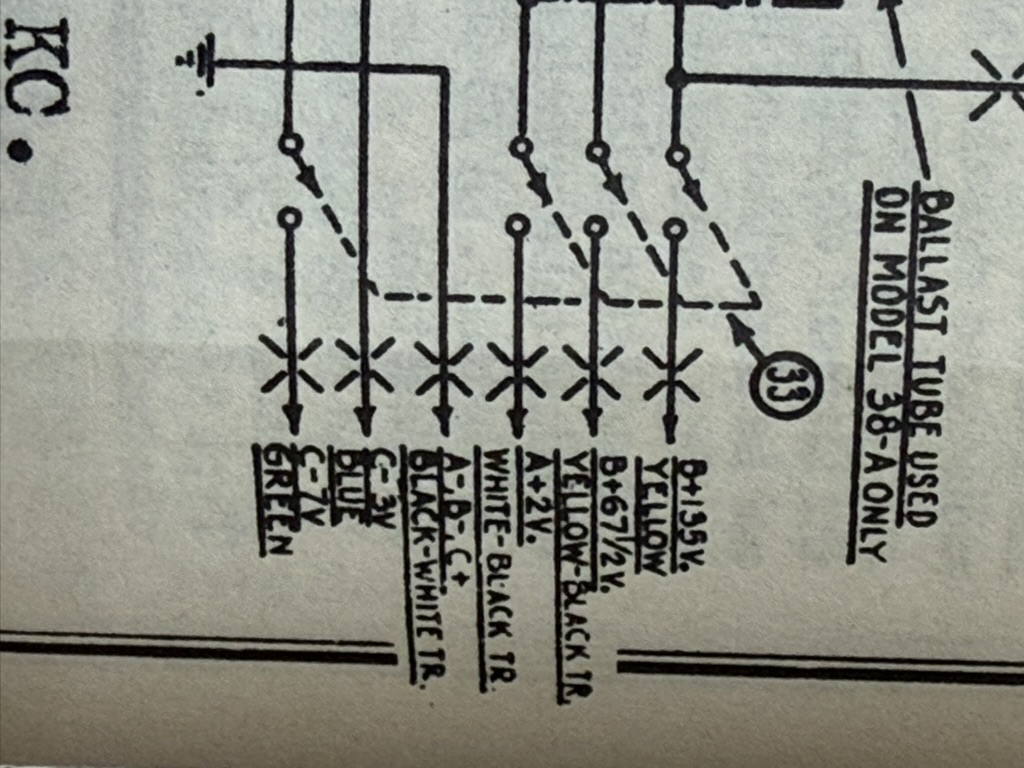
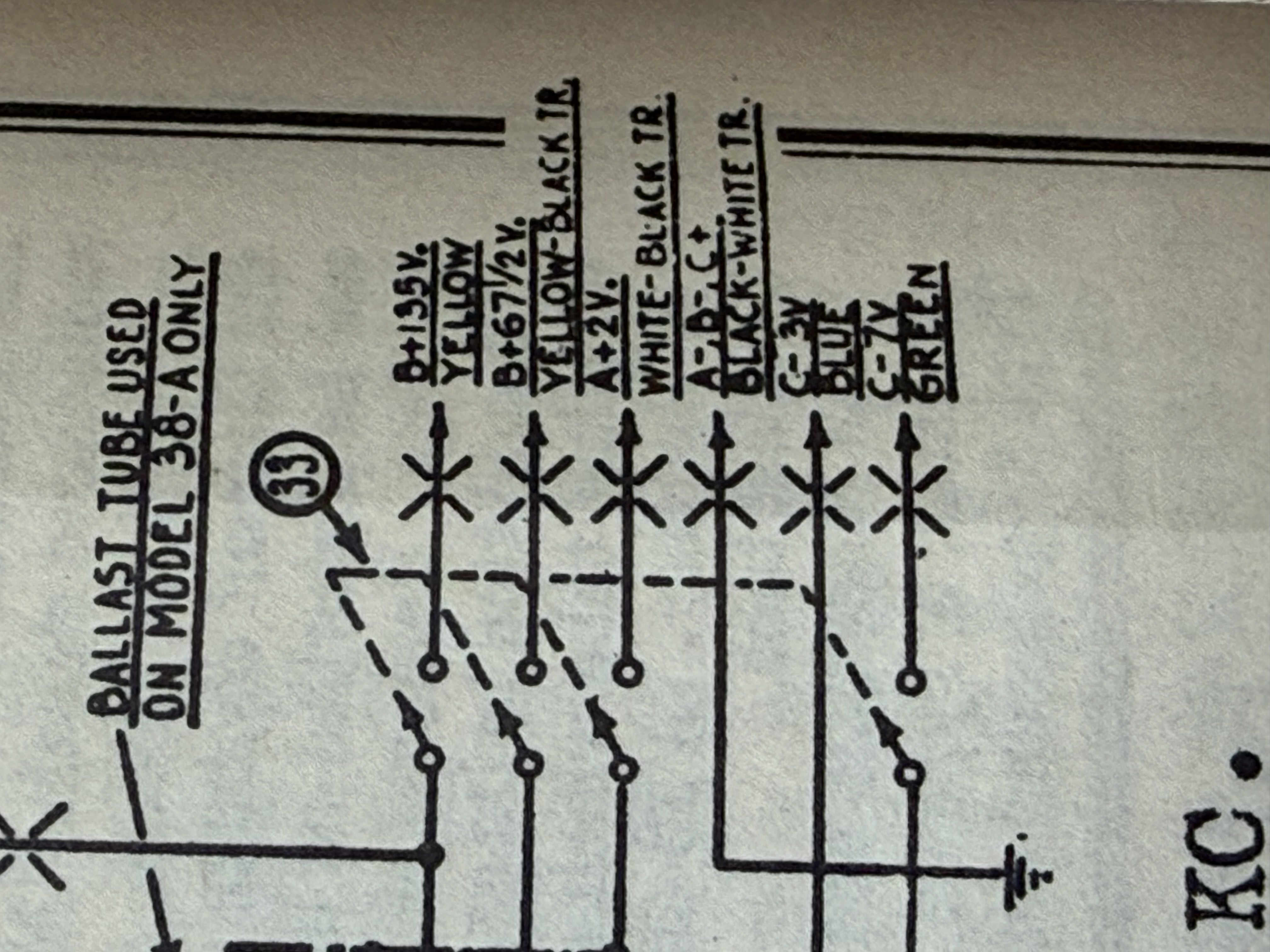
Thanks Mike, I mis-read the pot value, my bad. One thing that is still confusing me on the Model 38: the schematic shows the 6 pin connector for the input voltages from the battery. It shows 6 inputs. The ground and 2v is clear. But there are two B+, one at 135v and one at 67-1/2v. And two C one at -3v and one at -7v.
I get the different needs for plates vs screen grids, and different negative bias levels. But doesn’t this imply a need for 5 different input voltages? I’m not certain every pin is utilized on the connector I can double check that. But if there is a need for 5 input voltages what power supply provides that?
Craftsmanship is an ongoing cycle of learning fueled by patience, persistence, and care, where every project refines our judgment and challenges our skills, in the steady pursuit of the Path to Mastery.
(This post was last modified: 04-27-2026, 10:04 PM by SRv2.)
Posts: 18,427
Threads: 622
Joined: Oct 2011
City: Jackson
State, Province, Country: NJ
Well, yes it seems like you do.
I never worked with these radios, but the 67V is the 2nd DET B+ (detectors are often supplied with lower voltages), -3V is the pushpull grids' bias and -7V is the pushpull driver and the DET-OSC grids' bias.
Good news is, the neg. biases as well as the Det B+ do not draw a lot of current, especially biases.
And 67-1/2 V is there for a reason - it is middle of the 135V, so they probablyt use two sets of the same batteries and take the 67-1/2V from where they connect to each other.
People who do not drink, do not smoke, do not eat red meat will one day feel really stupid lying there and dying from nothing.
Posts: 5,652
Threads: 56
Joined: Sep 2008
City: Sandwick, BC, CA
The end of the cable on that Philco looks like a tube base, unless it has more fat pins then usual. It also looks like it has seven pins, so basically the same base as a 6A7 tube, so an old style seven pin socket may work in the battery eliminator. One plan I saw for a battery eliminator was in an old magazine I have, they used the same trick they used in early AC radios by tapping into the negative leg of the B supply with a voltage divider resistor, basically the divider was between the B- point and the center tap of the high voltage winding of the power transformer. It's not actually a negative voltage as such, but that the B- is more positive, so it works out about the same. The more modern way would be to use a lower voltage transformer, and reverse bias the rectifier diodes. It isn't that it's that complicated to make with all new parts, but I think it's more fun to make ones out of salvaged parts if you can get away with it.
67.5 volts is 1/2 of 135 volts, but 135 volts is also 3 X 45 volts, so many sets used the configuration of 45, 90, and 135 volts as well, and if you look at the tube manuals many of the power output stages also have a 180 volt rating, which is 4 X 45 volts, and some higher end battery sets did do this, at least in Canada. I have no idea if any in the U.S did this, I haven't really perused through the Riders to find out, though Sears or Montgomery Ward may have. I think the logic may have been to just offer a 6 volt vibrator model to those whom wanted a higher performance farm set. Unlike solid state equipment I think that the B+ voltages in farm sets may have had more to do with configuring, and packaging multiples of 1.5 volt cells in series then critical operating voltages. Obviously you would not want to exceed the recommended filament voltages, but running the B+ a little high would no blow anything up, in three way portables the B+ was often as high as 100 volts in AC mode.
Regards
Arran
Users browsing this thread: 1 Guest(s)
|
|
Recent Posts
|
|
Philco P45-6365 Universal Transformer Instruction Manual
|
| Can anyone guide me to where this may be found?GRG — 03:00 PM |
|
54C Complete Teardown/Rebuild
|
| I don't think that I have encountered a 12Z3 before, curious how it uses one of those but includes a #43, which is a 25 ...Arran — 02:17 PM |
|
HiFi (Chifi) tube amp build - but my own design.
|
| It's the other forum. I'm also in DIY, but mostly read there. Honestly, I kinda jumped into this without much thought to...TV MAN — 10:43 AM |
|
Philco 71 Code 125
|
| Hello,
I am in need of a schematic for this radio. Mine has the three separate circular tube shields and a shadow me...dconant — 08:06 AM |
|
Stromberg Carlson 1500 Squeal
|
| And life just keeps getting more complicated.dconant — 07:57 AM |
|
54C Complete Teardown/Rebuild
|
| Hello Roy,
here is this one
sincerely Richardradiorich — 12:45 AM |
|
54C Complete Teardown/Rebuild
|
| Richard,
Had grabbed it already but thank you just the same. I find myself wanting to find some way to block out the...glyphmon — 12:03 AM |
|
54C Complete Teardown/Rebuild
|
| Hello roy,
here is a link to the schematic .
Sincerely Richardradiorich — 11:54 PM |
|
54C Complete Teardown/Rebuild
|
| Richard,
The Silvertone 2014 also is a transformerless set, so I am incorporating a 1:1 600 ohm audio isolation transfo...glyphmon — 11:37 PM |
|
Preliminary work on wife's Silvertone 2014
|
| Did an alignment today which was interesting. IF alignment went great, almost all was already spot-on. Adjusting on th...glyphmon — 11:35 PM |
|
Who's Online
|
There are currently 1808 online users. [Complete List]
» 2 Member(s) | 1806 Guest(s)
|
|
|

|
 
|