RCA 6K3 Preliminary Capacitor/Resistor Research
Posts: 172
Threads: 10
Joined: Mar 2026
City: Franklin
State, Province, Country: Maine
Interim test point reached.
I wanted to do this in more granular stages, but I also wasn't going to redo soldering any more than absolutely necessary.
Replacements done so far:
All (3) electrolytic capacitors, C16, C30, C31
1 paper capacitor, C32
Resistor in IF can, R5
Resistors on top of the tuning condenser, R2, R19
Candohm (R14, R15, R16, R17, R18)
6F6 and 6H6 ordered NOS and installed (missing when I acquired the radio)
Any disturbed wire with crumbling insulation has been replaced, more to come, even if I don't otherwise need to disturb it
Put a fuse on the hot side of a new polarized power cord and from there to the switched connection on the power switch
Checked for shorts and resistance on the transformer and those tests showed the expected ohms
Remaining replacements:
7 paper capacitors, C15, C19, C24, C25, C27, C28, C29
1 resistor, R13
One thing I noticed however was when I was testing the connection through the power cord to the back of the power switch (switched connection to transformer) was that no matter what position the switch was in, there was a connection, so "OFF" doesn't seem to actually cut the current. Varying levels of ohms, but always a low, measurable amount.
So with that said, I did a gentle power-on with radio into dim-bulb into Isotap. Ramped power up to 120V gradually, with bulb increasing in brightness, but never reached anywhere near full-bright. No magic smoke, no fireworks, so initial win. Removed bulb from circuit and again ramped up power to 120V again.
Dial lights came on and made it to full brightness. Speaker was essentially completely silent, but when on close-to and full power, fiddling with the volume knob led to crackling noise while I was adjusting it, but returned to silent after. I took this as another win because "speaker can make noise". But that being said, absolutely silent otherwise - not even any hum. Tuning in one direction or the other had absolutely no effect, even switching bands was silent. As expected, the power switch (also tone control, 4 positions) didn't cut power in any position.
So, obviously I will continue on replacing the remaining paper caps that need to be done and the one remaining out-of-spec resistor and I'll test it again after that, but I'm thinking there's probably something else awry.
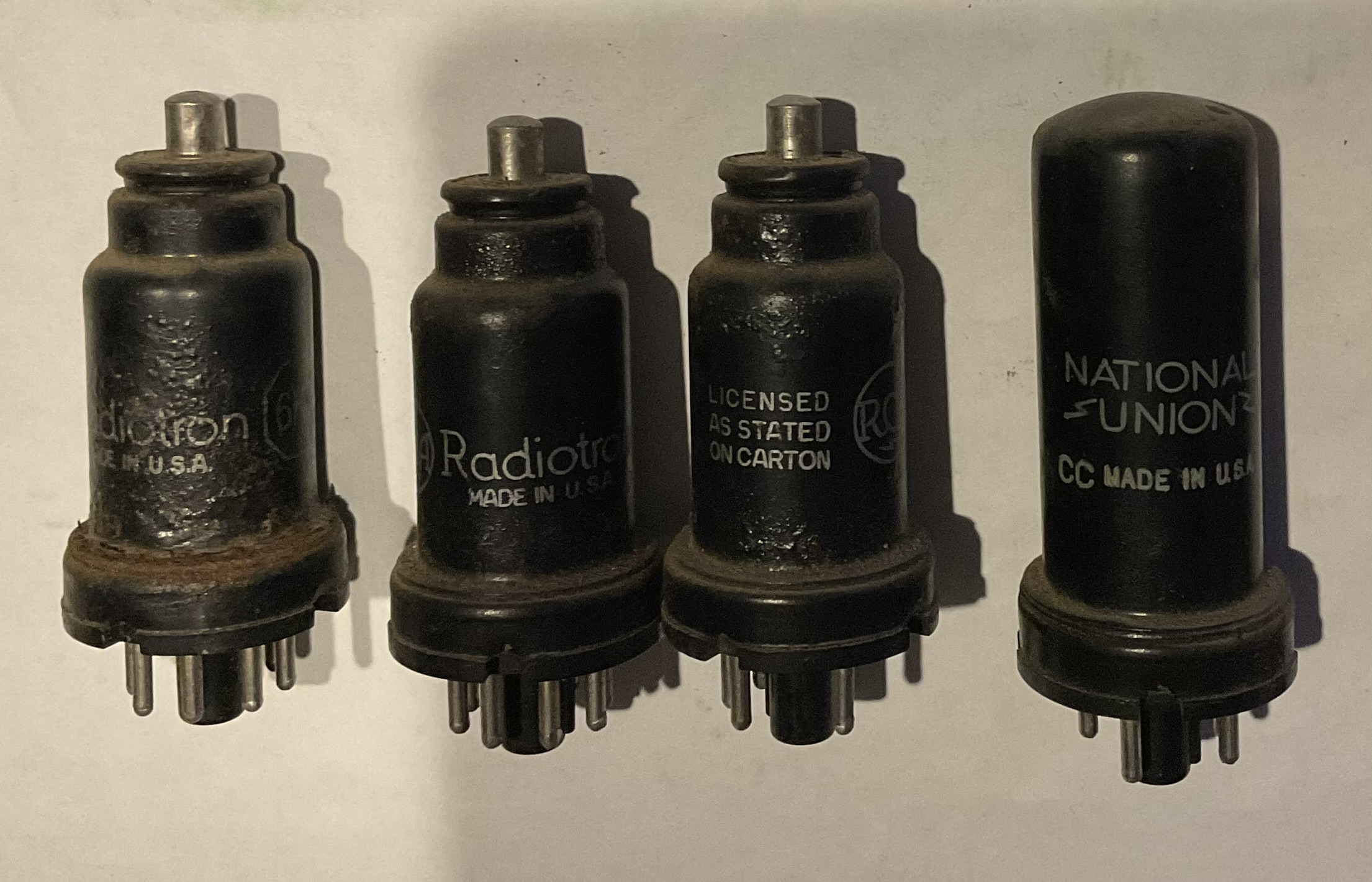
I've never done much voltage checking, but I suspect that's a next step for diagnostics. Anything else I should be checking at this point? Absent a tube tester, should I just order a set of the other tubes that were present in the radio when I got it? I feel like three of these (6K7, 6A8, 6F5) may be original as they are all RCA Radiotron branded and the 6K7 is even rusted with bubbling paint. The 5W4 rectifier (National Union) looks to be in good physical shape, but of course they're all metal so the only things visibly glowing in the radio are the dial lamps.
As for the power switch, is it likely to be the case that it is salvageable or should I be looking for a replacement? I'd kinda like to be able to turn it off.
Best wishes,
Roy
Posts: 18,427
Threads: 622
Joined: Oct 2011
City: Jackson
State, Province, Country: NJ
You have to suppress that itch to power on the radio that has not been fully recap.
Go have a shot, have a snack, watch a movie, but do resist that urge.
It is unhealthy and will not do you or the radio good.
People who do not drink, do not smoke, do not eat red meat will one day feel really stupid lying there and dying from nothing.
Posts: 2,327
Threads: 23
Joined: Jul 2020
City: Greenlawn
State, Province, Country: NY
Hi Glyphmon,
+1 on Morzh's comments. Most caps are either for filtering the output of the rectifier (the electrolytics and C32), Audio stage coupling (C27, C24), Tone control (C25, C26)parasitic oscillation suppression (C29 across the output transformer primary), Decoupling (C15), tank circuits, etc. If C27 shorts or leaks, this can cause the output tube or output transformer to burn up due to excess current. A shorted C29 will bypass the output transformer. I strongly recommend that these caps be replaced, as they are almost 90 years old and do leak, short, etc. The various trimmers and mica caps generally don't require replacement.
After replacing the rest of the caps indicated above, ohm the output transformer primary (between the screen and plate of the 6F6 (Pins 3 and 4).
One "divide and conquer" spot is the Phono input on the back of the radio. For radio, the link should be between 1 (output of the detector) and 2 (input of the amplifier). By opening that link and connecting an audio source between pin 2 (audio in) and pin 3 (chassis ground), you can verify that the amp works. If the audio inputted through the phono input is not heard through the speaker, then troubleshoot the audio and power spply circuits. If Audio is heard, then jumper pins 1 and 2 together and troubleshoot the "radio" section of the radio (Oscillator Mixer, IF and detector).
One possible (or probable?) failure is the "Voltage Divider Resistor", R14-R18. If this resistor opens, especially if R14 or R15 opens, cathodes of all tubes other than the rectifier and detector will not be at their correct potential, will float to B+ level and there will be no sound. If R16, 17 0r 18 opens, B+ or screen voltages will be lost. If you replaced them, good. That is where you want to start, when verifying voltages, in case of a cold joint or miswire.
"Do Justly, love Mercy and walk humbly with your God"- Micah 6:8
"Let us begin to do good"- St. Francis
Best Regards,
MrFixr55
Posts: 172
Threads: 10
Joined: Mar 2026
City: Franklin
State, Province, Country: Maine
MrFixr55 and Mike,
Understood about recapping but a question - as much as I have seen the advice about not turning on until recapped, I have also seen advice against "shotgunning" the repair and doing all the replacements at once with a number of people just doing the recapping in stages with power-on tests in between. So is shotgunning the electrolytic and paper caps considered the good and proper way, and all other components should be done and tested incrementally? It seems there are two schools of thought and I'm not trying to be argumentative, but would like to get some clarity. Or am I misunderstanding the meaning of "shotgun" in the repair process?
For what it's worth, I think a number of these capacitors had been replaced already at some point, though still very old and still/again in need of replacement. There were many leftover pieces of prior component leads that were just soldered over with new.
With that said, I went through and did the remaining 7 capacitors and 1 resistor. Repeated my power-on procedure from before with the same result - silence, except for noise when adjusting the volume control, slight pops when switching among the tone control and power settings, and between band changes. Again, no appreciable hum.
As for your troubleshooting steps, MrFixr55:
When ohming the output transformer, is it equivalent to test the contacts at the output transformer itself? This is a big speaker, I suppose relatively speaking, and so far have not taken it from the cabinet, but put the chassis back in and reconnected for the power-on tests. With the chassis back out, testing pins 3 and 4 on the 6F6 yielded no connection (infinite resistance, I guess) but again, the speaker was unplugged from the chassis. Testing the pins at the socket on the speaker yielded:
Pins 1 to 3: 360 ohms
Pins 2 to 3: 961 ohms
Pins 1 to 2: 1322 ohms
I will need to search for a sacrificial audio cable tomorrow (later today) to do the phono input test. I presume for the purpose of this test, we don't need to worry too much about stereo vs mono signals - garbled audio is still audio?
As for the voltage dividing resistor (candohm), yes, that has been completely replaced. I did test for continuity across the far ends of the things wired to the specific junctions to the leads of the individual resistors themselves, pre- and post-soldering, so I'm reasonably confident about these solder joints, but if it comes down to it, I will test there. I'm just trying to put off taking that speaker out as long as possible. It's nice that the 6K3 has a disconnect, unlike my 37-620, but it's only so long. An extender would make my life easier, but I'm not there yet either.
Best wishes,
Roy
Posts: 18,427
Threads: 622
Joined: Oct 2011
City: Jackson
State, Province, Country: NJ
Roy,
I will be very, very blunt about it, even if it does not sit well sith some folks (it seems here on Philco Phorum most of us understand this).
People who advocate against "shotgunning" (and let's be clear what I consider "shotgun repair": in my book it is "yank ALL capacitors and old resistors", which is ... not optimal, let's call it that) in the sense "only replace paper caps that are well out of range etc" are purists who let their purism get ahead of common sense and sound engineering / circuitry understanding judgement. Worse yet, they might have no such understanding in the first place.
Now. A capacitor, unlike resistors, ages due to chemistry change. Resistors age due to oxidation, contact of the carbon rod to the leads deteriorating etc. It is not dangerous but could unimprove the radio performance or stop it from performing altogether (like that - 10K, is it?- resistor in the oscillators) or if it is a bias-forming resistor that drifted too far. But it is unlikely to redplate your tube, blow your power supply, or just short the B+ and get something smoking. Which is what an old paper capacitor can do.
The chemistry change in them results in two things:
1. Most important: leakage. Meaning, the capacitor develops excessive conductivity at DC, which an ideal cap does not have and a real world cap has so little (if it is ot an electrolytic) we do not need to worry about it. The old paper cap most often has quite measurable leakage. It depends on brands, some (like German ERO), are real bad, some like old american caps, are better. But still leak.
This results in, for example, in case of DC blocking cap, in not fully blocking that DC, which will change the bias of the tube that is after that capacitor.
In case of bad leakage and he cap being the DC filter, it could smoke a resistor, or, if used in parallel to the electrolytic Power supply filter, killing the rectifier tube, filter choke / field coil if used as such.
They also used them as input DC line filters, and this is just plain dangerous (death capacitor).
Now, is there a mathematical probability that a capacitor somehow survived and is still good?
Sure. 0.1% at best.
Is it worth the risk? No.
Is it worth extra troubleshooting when you do not know what is wrong, and one of these is the culprit? No.
2. They also drift quite a bit. Usually it shows up as an increased capacitance. From 100% increase in american caps to 600% increase in those aforementioned EROs. This, simply speaking, results in some circuits not performing according to their intended operation.
Part of this is also the leackage: it does show as the capacitance increase.
There are other things like the loss tanget increase (same reason, chemistry change), etc etc.
And I intentionally omit the electrolytic caps. I hope we have an understanding about these: they just have to go without discussions and explanations. Because the electrolytic capacitor by definition is a limited lifetime device, with the typical today caps (at the max ripple/voltage) being 1,000hr and the best are 10,000hr. Today's. Not those made in 1930s, which they were just learning about how to make'em.
The ONLY type of capacitors to be left alone and not touched are the mica capacitors. They do not age. They do not change values or parameters. The only reason to change one is as the result of troubleshooting confirming the cap is bad, and I am yet to see one fail.
Now, because in this country we have the 1st Amendment and such, people have the right to be wrong.
My experience (both as a restorer-hobbyist and an electrical engineer (I am and still practice)) can be formulated like so:
Without known confirmed working components any troubleshooting is a waste of time.
I make sure all my electrolytic caps and paper caps are replaced.
I make sure all of my resistors are within tolerance or, in non-critical circuits, close enough to the specs.
I check all my tubes prior to inserting them back.
I make sure my transformer is good (the first thing I do, in fact, because otherwise it is like reviving a patient whose heart has been removed).
Then (I might forget less important things I do prior to the power up) I can do the Variac power-up.
PS. There are people in this world who believe in Oxygen-free copper, normalized impedance transmission line audio cables, breaking in these cables, and, amongst other things - in leaving the paper caps in until proven guilty. They are likely good people and I respect them, as people. I also think their understanding of the process (they might have tons of experience, but I am talking about understanding) is garbage and you would do yourself a big favor if you politely listen to them (no reason to make enemies) and then forget what they told you.
Amen.
People who do not drink, do not smoke, do not eat red meat will one day feel really stupid lying there and dying from nothing.
Posts: 431
Threads: 9
Joined: Apr 2023
City: Roanoke
State, Province, Country: Virginia
I absolutely concur with morzh. He is speaking, as many of us here speak, based upon decades of experience. There are people who say that bumblebee caps are the greatest thing in audio amplifiers. I have seen far too many failed bumblebees to ever trust them in any circuit. You have to understand the experience level of a person to trust their recommendations.
Dale H. Cook, GR/HP/Tek Collector, Roanoke/Lynchburg, VA
https://plymouthcolony.net/starcity/radios/
Posts: 3,187
Threads: 226
Joined: May 2008
City: Omak
State, Province, Country: WA
I agree, and one great thing about this forum is that everyone has an area of expertise they specialize in.
Sincerely Richard
Posts: 172
Threads: 10
Joined: Mar 2026
City: Franklin
State, Province, Country: Maine
Mike and Dale,
I thank you for your grace in answering the question. I have a clearer understanding of how the capacitors fail. I'm surprised to see how few hours we are to expect from even new electrolytic capacitors - yikes, I'd have thought we'd be further along than that now. Obviously, they are not necessarily running at full bore all the time, but still.
I suppose I had taken a narrower view of "shotgun" thank Mike's, which is why I asked about people's definition of that term.
I understood (prior to asking the question) that for restoration, we NEED to change, at a base level, both electrolytic and paper capacitors and resistors that are out of tolerance and that we DO NOT change Mica capacitors and as well as resistors that test, out of circuit, within 20% of intended value. I had taken shotgun to mean replacing all of the components in the NEED category in one fell swoop without diagnosis or testing, which while accomplishing the needed replacements might allow the introduction of a fault (e.g., bad solder joint), and would then be harder to identify/track down, down the line rather than if done in small increments between tests. My definition did not include replacing components in the "don't replace" category, hence, why definitions are important.
So, yes, I agree, and it is what I did on my Philco radio before: ensure all electrolytics and paper capacitors, at a minimum, will be replaced before any testing on power. This will, without fail, be my process going forward.
Mike, I will say that I'm a little surprised if this response is you being "blunt". I don't know your full story, but my wife is Romanian having worked with many different eastern Europeans over the years (mostly south-eastern), one thing I know is that they know how to be blunt. This was downright polite. And Dale, agreed about understanding the experience level, but unfortunately there are many examples of people "doing things" on the internet which is the primary resource I would say most of us new to this interest have, and credentials are not necessarily obvious or readily identifiable, which is why, when a discrepancy comes up between the practices of different individuals arises, I ask the questions.
I will try the phono input test as suggested by MrFixr55 and report back for any further guidance/clarification.
Best wishes,
Roy
Posts: 4,832
Threads: 437
Joined: Jun 2011
City: Boston
State, Province, Country: Massachusetts
Wow Mike you are a great writer! Maybe you should do a radio web site like Phils Old Radios, keep you busy when you retire. I have spoken to many folks who are excellent radio repair/restoration technicians. Mike is echoing what I have heard so many times.....Paul
Tubetalk1
Posts: 1,797
Threads: 55
Joined: Feb 2015
City: Roseville, MN
So now that you've learned all there is to know about paper caps, it appears no one answered the question regarding the power switch. Here's what I would do. Since the switch is not even intermittent, something is shorting it or the spring mechanism is so dirty it can't do it's thing. Spray some solvent, like WD40 or alcohol, into the switch. You'll have to look closely to find openings. Put an ohmmeter on the switch contacts and work the switch 100, times. If it hasn't changed then do it again and leave it sit for a while. Try again. When the switch works properly, wash it out with electronic cleaner or alcohol, let it dry then I use Deoxit D5.
And remember, those paper caps are made of paper, 85 - 90 years old. Have you seen what a 90 year old newspaper looks like?
Posts: 18,427
Threads: 622
Joined: Oct 2011
City: Jackson
State, Province, Country: NJ
Rod,
I think what confuses some folls is, "this paper is a special kind of paper, it is impregnated with special compounds and oils".
Heck yeah, papyrus, that is some of the docs written on it, have survived for thousands of years. Though I would not use that one for making capacitors.
Paul,
My son says I am a very bad teacher. The reason is, I (I actually have my education in physics and part of it was, they were prepping us for being teachers in schools; and during the practice I was singled out as the best of the group) am very methodical in my explanation. Borderline (sometimes downright) droning. And, I require my student to know his basics, as without it there is no teaching any further; so when the student (son/daughter, as I do not teach otherwise) simply wants me to solve the problem or do shortcuts, I refuse.
Perhaps, because of this my being methodical, though lengthy, my writing sometimes is easy to understand as I do not skip things without which that, what is being explained, would not be able to be understood.
PS. English being my second language helps. I try not to (though I can) make the language excessively flowery or studded with idioms. That is, when I explain things. My way is, I am actually explaining it to myself as to a dumb/fresh student. If I am satisfied, then I put it out.
PPS. O. Henry is my favourite (well, one of the favourite) writer, and, knowing what real writing is like, I will spare the literature buffs from the throes of reading my verbal diarrhoea.
Roy,
My version of "blunt" is, I do not beat about the bush, trying to tell what I think and at the same time not to hurt anyone's feelings, when we are talking about facts, not the tastes.
The facts like, well 1) Ohm's law is the law, 2) Perpetuum Mobile is not possible, 3) paper capacitors from 30s today are a device which is physically different from what it was when it left the factory, 4) pure socialism/communism is not economically viable, and such.
Facts cannot hurt. Unless one tries to fight the facts.
As for the electrolytic caps, you are right, employing them at well below their max ratings prolongs life by orders of magnitude.
Roughly, the life of the cap DOUBLES every 10 degrees Kelvin (or C, same thing) dropping below the rated maximum. Think of it. If your rated temp is 105C and you bring it down to 65C, you prolong your cap's rated 2,000 hrs 16 times. 32,000 hrs. You have to run your set for 1hr for 100 years every day to meet this. And then there is also the Voltage factor. Which is, if it has effect, can be the Rated to Applied ratio to the degree up to 5. So, when you use your cap, rated at 500V, at 250V, 2.5 to the degree up to 5 (almost a 100) which is what you multiply your 32,000 hrs by. That is, 3,200,000 hrs. This thing will leave longer then us and our children, and grandchildren, combined. Of course, this is the first approximation.
And, another advantage of Voltage derating, though this is for ceramic MLCC caps: their capacitance at rated voltage could drop as far as to mere 10% of their nominal one. So, if you think you have an X5R 100uF cap rated at 6.3V and you use it to decouple (and as bulk) for 5V, you might have mere 15uF left.
Live with it now  
People who do not drink, do not smoke, do not eat red meat will one day feel really stupid lying there and dying from nothing.
Posts: 172
Threads: 10
Joined: Mar 2026
City: Franklin
State, Province, Country: Maine
Update after testing external audio: the speaker sings as beautifully as only an 89-year old speaker reproducing the right audio channel will allow with a little evidence of needing to clean the volume control. I was even able to test the tone control and could hear the difference so at least that also seems to be working.
So the silence is coming from the RF section it seems. The 6H6 (NOS from findatube) seems to be next in the chain backwards, is that where people would suggest we begin checking? The chart for voltages from the service notes file seems pretty straightforward.
Is it "simply" checking DC volts from the pins of the various tubes, most going to chassis ground except as otherwise indicated (plate and heater voltages checked pin-to-pin for AC)?
Best wishes,
Roy
Posts: 18,427
Threads: 622
Joined: Oct 2011
City: Jackson
State, Province, Country: NJ
>>as beautifully as only an 89-year old speaker reproducing the right audio channel will allow
I tell you this: a...let's see...89-year old speaker from the 37-116 (also, with different field coil, used in 37-690, 38-116 and 38-690), a 14" job, despite the age, will rival many a today's HiFi speakers. Which showed when I demoed my 38-690 to an unsuspecting visitor and they refused to believe that thing was built in 1938.
As for the DC volts, reading DC volts is almost like given a good first listen to "lub-dub" (aortic, pneumonic, Erbst point etc) a good doctor will always do, even if he is not a cardiologist. Basic things. Can tell a lot about the object of your research.
Voltages at the minimum will tell you:
1. If you have open circuits in RF transformers, resistor etc that connect plates to the B+.
2. Shorts (if the smoke hasn't told you so eloquently enough).
3. Wrong biases.
4. Bad parts (resistors and capacitors that leak).
5. And some other stuff.
So, yes. Go through the voltage charts and see if there are significant (not a few volts where it calls for 200V; while important, this is usually not the first thing of interest) deviations.
People who do not drink, do not smoke, do not eat red meat will one day feel really stupid lying there and dying from nothing.
Posts: 172
Threads: 10
Joined: Mar 2026
City: Franklin
State, Province, Country: Maine
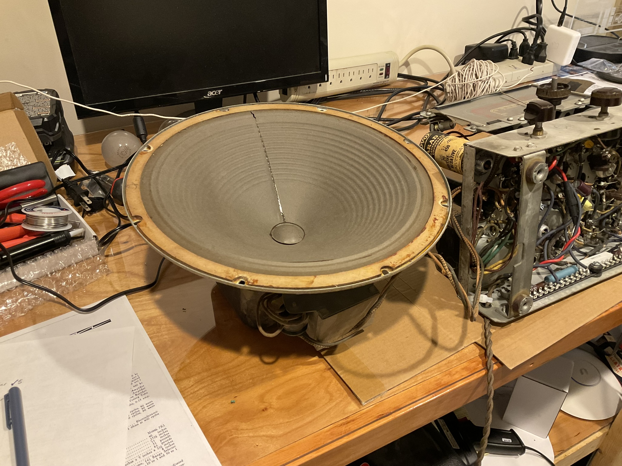
To be clear, I wasn't thinking that the speaker wouldn't perform well. I was more referencing the fact that it was doing the best it could with a single audio channel from an audio source likely not electrically ideal for the phono jack with a volume pot that needs cleaning. I think the speaker did beautifully all things considered. I believe it's in pretty good physical shape as well, having now removed it from the cabinet. Before we get to voltages, see below:
Voltages all tested except one (expected values in parentheses, significant deviations in bold):
6A8:
across heaters: 6.3V AC (6.3)
pin 1: 0V (0)
pin 3: 263V (264)
pin 4: 61.6V (100) 38.4% low
pin 5: -0.4V (-20*) ? - see note on asterisks
pin 6: 172.3V (170)
6K7:
across heaters: 6.3V AC (6.3)
pin 1: 0V (0)
pin 3: 263V (264)
pin 4: 61.6V (100) 38.4% low
pin 6: -3.97 (-3) 32.3% high
6H6:
across heaters: 6.3V AC (6.3)
pin 3: -4V (-3) 33.3% high
pin 4: -3.16V (-3)
pin 5: -0.798V (-0.3) 166 % high
pin 8: 0V (0)
6F5:
across heaters: 6.3V AC (6.3)
pin 1: 0V (0)
pin 3: 172.8V (170)
pin 4: 102.4V (80V / 115V*)
pin 8: 1.165V (1.2)
6F6:
across heaters: 6.3V AC (6.4)
pin 1: 0V (0)
pin 3: 251V (264)
pin 4: 266V (265)
pin 5: -17.5V (-0.5 / -16V*)
pin 6: -17.86V (-18)
5W4:
both plates to ground: 325V AC (355)
plate to plate: didn't test - anticipated 710V AC exceeds my meter's range
pin 1: 0V (0)
pin 8: 348V (340)
The asterisks are original to the diagram with the explanation that they represent the meter measurement while the non-asterisked number represents the value without voltmeter loading.
Observations about the significant deviations:
6A8 pin 4 and 6K7 pin 4 both share a connection to dogbone R4 (original, 22K spec, 21.3K measured in-circuit), and from there to electrolytic C16 (new), and from there to the oscillator coil.
6K7 pin 6 and 6H6 pin 3 likewise share a connection to R6 (original, 2.2M spec, 2.16M measured in-circuit), and from there to 2nd IF transformer
6H6 pin 5 is a bus connection to the 2nd IF transformer.
Thoughts?
Best wishes,
Roy
Posts: 431
Threads: 9
Joined: Apr 2023
City: Roanoke
State, Province, Country: Virginia
glyphmon Wrote: Thoughts?
Are you using a 1,000 ohms per volt AC/DC meter, as specified in the RCA service manual for the 6K3?
Dale H. Cook, GR/HP/Tek Collector, Roanoke/Lynchburg, VA
https://plymouthcolony.net/starcity/radios/
(This post was last modified: 05-10-2026, 05:17 PM by DaleHCook.)
Users browsing this thread: 1 Guest(s)
|
|
Recent Posts
|
|
under chassis parts locator diagram for 1938 Zenith 9s262
|
| Has anyone gone to the trouble of creating an under chassis parts locator image? Yes, I can identify components by foll...bobloney — 08:57 PM |
|
Plug Voltages Needed For A 1943 CRV-20130 Power Supply
|
| Try looking at this site the book mark is for a old generator that I was given. David https://radionerds.com/index.ph...David — 08:36 PM |
|
Plug Voltages Needed For A 1943 CRV-20130 Power Supply
|
| Hello Everyone,
I am looking for voltage identification for all the pin positions on the socket of a CRV-20130 power su...Tonym4704 — 08:16 PM |
|
Philco P45-6365 Universal Transformer Instruction Manual
|
| Can anyone guide me to where this may be found?GRG — 03:00 PM |
|
54C Complete Teardown/Rebuild
|
| I don't think that I have encountered a 12Z3 before, curious how it uses one of those but includes a #43, which is a 25 ...Arran — 02:17 PM |
|
HiFi (Chifi) tube amp build - but my own design.
|
| It's the other forum. I'm also in DIY, but mostly read there. Honestly, I kinda jumped into this without much thought to...TV MAN — 10:43 AM |
|
Philco 71 Code 125
|
| Hello,
I am in need of a schematic for this radio. Mine has the three separate circular tube shields and a shadow me...dconant — 08:06 AM |
|
Stromberg Carlson 1500 Squeal
|
| And life just keeps getting more complicated.dconant — 07:57 AM |
|
54C Complete Teardown/Rebuild
|
| Hello Roy,
here is this one
sincerely Richardradiorich — 12:45 AM |
|
54C Complete Teardown/Rebuild
|
| Richard,
Had grabbed it already but thank you just the same. I find myself wanting to find some way to block out the...glyphmon — 12:03 AM |
|
Who's Online
|
There are currently 1949 online users. [Complete List]
» 1 Member(s) | 1948 Guest(s)
|
|
|

|
 
|