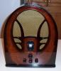
RCA 6K3 Preliminary Capacitor/Resistor Research
Posts: 172
Threads: 10
Joined: Mar 2026
City: Franklin
State, Province, Country: Maine
Okay, rookie mistake here, but I will also blame my 37-620 for giving me a false sense of expectations. The Philco made noise when I turned it on and the tubes warmed up, even if it wasn't a station, without an antenna connected. I expected this set to behave similarly.
Connecting an antenna brought noise to the AM band, especially depending on where on the band one tuned. Also needed to turn the volume up pretty high but, it was definitely producing variations in static as I adjusted the dial. There was a lot of activity (not necessarily understandable stations) on the upper bands of shortwave, not much on the lower bands, and when I went back through on AM I managed to find the one local AM station that I could reach with the Philco as well. I also was able to tune it to me my FM retransmitter so it is not, in fact, silent or deaf. I'm still in the market for an affordable new signal generator so at some point I will bite the bullet on that and attempt the aligment on both the 37-620 and this 6K3 and see what that does for them.
I'm still curious to know what you think about the voltages I reported, but it lives.
Best wishes,
Roy
Posts: 172
Threads: 10
Joined: Mar 2026
City: Franklin
State, Province, Country: Maine
Dale,
The tool I have presently at my disposal is an Extech MN35 DMM which I've had for other aspects of my work from before embarking on this hobby. I don't know that it has such a rating.
Best wishes,
Roy
Posts: 5,653
Threads: 56
Joined: Sep 2008
City: Sandwick, BC, CA
Speaking of shotgunning components, I've noticed a tendency to condemn all of the tubes in a device as the cause of a fault, in my experience tubes are seldom the failure, when I get a new set I check the tubes out of habit but have seldom found any that would prevent the radio from playing. In a series string set I will find ones with an open heater, usually the power output tube since they have the largest heaters, but not usually in a transformer set. One thing I have noticed is that certain tubes will wear out faster then others, depending on what they do, the mixer-oscilator/convertor tubes are one, first audio/second detectors are another, one that seems to last and last is an IF amplifier tube. In this set they used a 6H6 as a second detector/AVC tube, and a 6F5 as a 1st audio tube, and the 6H6 is another tube that seldom wears out. To be clear unless a tube has very poor emission, such as under 40% the set should still play, it just won't perform as well, obviously tubes with shorts in them, or open filaments will stop the set from playing at all.
The 6K3 is another model pulling what I call the "tube stuffing" scam, they added a 6F5 and a 6H6 where they could have used a 6Q7 or a 6R7 to do the job of both tubes, this was all too common in sets made around that time, and if they added a magic eye it was then a seven tube model, but in reality you were getting the equivalent of a five tube set. Instead of adding that tube they could have added an untuned RF amp, or an extra IF amp, with a minimum of extra parts, but I really think that the 6H6 was one of those tubes that was the answer to a question nobody was asking.
Also when I recap a set, I usually work my way through from one tube socket, or terminal strip, to the next, checking resistors, and replacing ratty wires as needed, it's much easier to keep track of the work I have been doing. In many AC/DC radios they have the filter caps mounted in a cardboard tube under the chassis, and I will often remove that first, and replace it last, as it's often in the way of accessing other components. I like to restuff the tube as it makes for a cleaner installation then trying to mount the caps under the tube sockets.
Regards
Arran
Posts: 172
Threads: 10
Joined: Mar 2026
City: Franklin
State, Province, Country: Maine
Posts: 431
Threads: 9
Joined: Apr 2023
City: Roanoke
State, Province, Country: Virginia
glyphmon Wrote: Extech MN35 DMM
That would appear to be a perfectly serviceable DMM, with 10 meg DC impedance and 4.5 meg AC impedance.
Very few of us use an actual 1,000 ohms per volt AC/DC meter. Although I own one in my Triplett 1167-A Set Tester, ca. 1935, I do not use it - my 1167-A is a shelf queen.
Any high-impedance DMM can easily be turned into a 1,000 ohms per volt AC/DC meter. Say you want to measure an expected DC voltage of 350 volts. You will use the 600 VDC range of your Extech. Multiply the maximum voltage of that range (600) times 1,000 ohms to get 600,000 ohms. If you shunt that value across the input of your Extech, you turn it into a 1,000 ohms per volt DC meter. A standard 5% 620k resistor will work well enough.
Just for giggles I like to have shunt boxes in the shop for my principal bench meters - a Keithley 4½ digit True RMS bench DMM, and an HP 427A analog multimeter. As a rule I almost never use those shunt boxes, because any decent high-impedance digital or analog meter should measure almost any voltage in an old radio chassis close enough for jazz, if a little high. The voltages you marked in boldface would seem to be definilty bad in any case, with the exception of the lowest voltages such as bias voltages. Those would likely read a lot closer with the loading of a 1,000 ohms per volt DC meter.
You need to work backwards from the bad readings toward the power supply to figure out what is causing the bad readings. A set whose paper and electrolytic caps have all been replaced, whose tubes do not test bad, and whose inductor and transformer windings have been correctly ohmed out, will be easier to troubleshoot.
Dale H. Cook, GR/HP/Tek Collector, Roanoke/Lynchburg, VA
https://plymouthcolony.net/starcity/radios/
(This post was last modified: 05-10-2026, 06:43 PM by DaleHCook.)
Posts: 431
Threads: 9
Joined: Apr 2023
City: Roanoke
State, Province, Country: Virginia
glyphmon Wrote: I understood (prior to asking the question) that for restoration, we NEED to change, at a base level, both electrolytic and paper capacitors and resistors that are out of tolerance
I change all old electrolytics and paper caps period. Even if some test okay (are you measuring capacitor leakage at rated voltage?), they may be disasters waiting to happen. When I restore a set I want it to keep working indefinitely. Replacing the parts which are most likely to fail is for me worthwhile to prevent possible later failures.
Dale H. Cook, GR/HP/Tek Collector, Roanoke/Lynchburg, VA
https://plymouthcolony.net/starcity/radios/
Posts: 18,427
Threads: 622
Joined: Oct 2011
City: Jackson
State, Province, Country: NJ
Arran
The very first thing I do, before even starting cleaning the chassis, is testing the tubes.
And while I have to admit it is not many of them that are bad, I get bad ones every other set. Except the 38-12 series and likes: even with shot rusty chassis in a totally in-shambles case, the tubes were always OK.
"Bad" can be anything from Zero emission or VERY weak to an open filament or internal inter-electrode short. Couple of gassy ones.
People who do not drink, do not smoke, do not eat red meat will one day feel really stupid lying there and dying from nothing.
Posts: 1,797
Threads: 55
Joined: Feb 2015
City: Roseville, MN
First impression: looking at the voltages on the 6A8 and the symptoms I'd say the oscillator isn't running.
Posts: 431
Threads: 9
Joined: Apr 2023
City: Roanoke
State, Province, Country: Virginia
In the OP's shoes the first thing I would do is look at things with a 'scope, but I don't think he owns one. A 'scope has been my most versatile and powerful diagnostic tool for 50 years. It was necessary for my work years before I began restoring radios.
Dale H. Cook, GR/HP/Tek Collector, Roanoke/Lynchburg, VA
https://plymouthcolony.net/starcity/radios/
Posts: 172
Threads: 10
Joined: Mar 2026
City: Franklin
State, Province, Country: Maine
Quote:I change all old electrolytics and paper caps period. Even if some test okay (are you measuring capacitor leakage at rated voltage?), they may be disasters waiting to happen. When I restore a set I want it to keep working indefinitely. Replacing the parts which are most likely to fail is for me worthwhile to prevent possible later failures.
Dale, allow me to clarify, the "... that are out of tolerance" was specifically meant for the resistors. All electrolytics and paper capacitors are understood to need replacing. I do not test them.
By "shunting across" with the DMM, I take it you mean to have the resistor in series between the test lead and the point in the radio under test?
The current status of this set is: all electrolytic and paper capacitors replaced, out of tolerance resistors replaced, two NOS tubes (6H6 and 6F6) installed to replace completely missing ones, no other tubes having been tested (I own no tester at present). Could I bother you for specifics on ohming out inductor and transformer windings? I may have done some of this already but again, I want to be sure of my understanding of the terms and process. In working back toward the power supply, in the case of the two 61.6V instead of 100V readings, would it be back to the resistor, then to the electrolytic, etc?
The voltages are as followed:
at the pins as tested, originally 61.6, now 63.5 for whatever reason
on the tube-side of resistor R4 (22K ohm), 63.3
between R4, electrolytic C16, and connection to oscillator coil, 175.5
at the R14/R15 junction on the candohm, 174.2
at the end of the candohm, 265
Arran, do you have any suggestions for specific tube testers that I should be on the lookout for? As above, I don't have a tester now, though there was a Kickok on eBay I was watching that ultimately went for around $150 plus shipping just a couple nights ago.
Rod, as I am now, with antenna attached able to receive some stations, would you still say the oscillator isn't running?
Thank you all again for your guidance in making this set all that it can be.
Best wishes,
Roy
Posts: 4,832
Threads: 437
Joined: Jun 2011
City: Boston
State, Province, Country: Massachusetts
Many old timers have a sequence in their work, check tubes first, if you need to order new you can be waiting on them and working on other sections.
Tubetalk1
Posts: 1,797
Threads: 55
Joined: Feb 2015
City: Roseville, MN
Well, you would be correct, Roy. I must have skimmed past that fact while jumping around the fluff. I'll regroup and reread all of today's posts.
BTW I own a tube tester and have used it once this year.
(This post was last modified: 05-10-2026, 09:35 PM by RodB.)
Posts: 431
Threads: 9
Joined: Apr 2023
City: Roanoke
State, Province, Country: Virginia
glyphmon Wrote: By "shunting across" with the DMM, I take it you mean to have the resistor in series between the test lead and the point in the radio under test?
A shunt is in parallel with something else. In this case the shunt resistor is across the DMM input, in parallel with the signal coming from the test leads.
glyphmon Wrote: ... do you have any suggestions for specific tube testers that I should be on the lookout for?
Bear in mind that no tube tester can tell you that a tube is good, it can only tell you when a tube is definitely bad.
I use two tube testers - a Hickok 533 for small-signal tubes, and an EICO 625 to check emission in power tubes.
Dale H. Cook, GR/HP/Tek Collector, Roanoke/Lynchburg, VA
https://plymouthcolony.net/starcity/radios/
(This post was last modified: 05-10-2026, 09:37 PM by DaleHCook.)
Posts: 18,427
Threads: 622
Joined: Oct 2011
City: Jackson
State, Province, Country: NJ
>> By "shunting across" with the DMM, I take it you mean to have the resistor in series between the test lead and the point in the radio under test?
Well...shunt is by definition is in parallel to what it shunts.
If you shunt a coronary artery, you put a new vessel (a piece of a vein from your leg) in parallel to the clogged artery.
The very word "shunt" acquired its latest meaning in 19th century from railroad use meaning "directing around / redirecting".
The thing in series is called "ballast."
As for the tube tester, mine is Hickok 600A which is, along with 800, are not that different from 533.
As Dale said, these MCTT (mutual conductance tube testers) will not tell you the tube is good. For instance, they do not measure leakage. Which, in some cases, like a unity gain power stage, where everything is DC-coupled, (I personally fell victim to oone such case) is very important. But if the tube is bad bad, it will tell you. Inter-electrode shorts, open filament, no emission, gas inside, weak - you will have these data. And in most cases this is enough, at least to start with.
People who do not drink, do not smoke, do not eat red meat will one day feel really stupid lying there and dying from nothing.
Posts: 172
Threads: 10
Joined: Mar 2026
City: Franklin
State, Province, Country: Maine
Because I'm still new at this, I will plan to consult you fine folks when it gets time to need to do the shunt thing to make sure I understand which pieces go where.
As for tube testing not being able to tell you a good tube, but instead a bad one, I'm sure it's analogous to many procedures, like memory testing in computers, in that it only guarantees that a "fail" result corresponds to a bad component. Even so, I know there are certain units based on their sensitivity that might fail tubes that are otherwise quite usable. I'll keep on the lookout for a tube tester that hopefully won't break the bank.
If anyone has thoughts about the voltages I listed (traced back to the voltage dividing resistor) let me know. It looks like 265V going in at the far end of R14 (3.5K ohms) the beginning of the candohm, with 175V coming out at the junction with R15. I think that's about right. Given that I measured (in the first round of testing) 172.8 on pin 3 of the 6F5 while it was expecting 170 from the R14/R15 junction, and that's the same source as the 175 I'm seeing heading into R4, but only 61 to 63 at the 6A8 and 6K7, is it likely that, although testing at 21.3K ohm (in-circuit) that this R4 actually is the culprit? I'm struggling to wrap my head around what I know should be a relatively simple calculation as to how we get from the 175 or so volts on one side of R4 to the other side to a specific value on the other side, headed to the tubes (100 being expected in this case).
Best wishes,
Roy
Users browsing this thread: 1 Guest(s)
|
|
Recent Posts
|
|
under chassis parts locator diagram for 1938 Zenith 9s262
|
| Has anyone gone to the trouble of creating an under chassis parts locator image? Yes, I can identify components by foll...bobloney — 08:57 PM |
|
Plug Voltages Needed For A 1943 CRV-20130 Power Supply
|
| Try looking at this site the book mark is for a old generator that I was given. David https://radionerds.com/index.ph...David — 08:36 PM |
|
Plug Voltages Needed For A 1943 CRV-20130 Power Supply
|
| Hello Everyone,
I am looking for voltage identification for all the pin positions on the socket of a CRV-20130 power su...Tonym4704 — 08:16 PM |
|
Philco P45-6365 Universal Transformer Instruction Manual
|
| Can anyone guide me to where this may be found?GRG — 03:00 PM |
|
54C Complete Teardown/Rebuild
|
| I don't think that I have encountered a 12Z3 before, curious how it uses one of those but includes a #43, which is a 25 ...Arran — 02:17 PM |
|
HiFi (Chifi) tube amp build - but my own design.
|
| It's the other forum. I'm also in DIY, but mostly read there. Honestly, I kinda jumped into this without much thought to...TV MAN — 10:43 AM |
|
Philco 71 Code 125
|
| Hello,
I am in need of a schematic for this radio. Mine has the three separate circular tube shields and a shadow me...dconant — 08:06 AM |
|
Stromberg Carlson 1500 Squeal
|
| And life just keeps getting more complicated.dconant — 07:57 AM |
|
54C Complete Teardown/Rebuild
|
| Hello Roy,
here is this one
sincerely Richardradiorich — 12:45 AM |
|
54C Complete Teardown/Rebuild
|
| Richard,
Had grabbed it already but thank you just the same. I find myself wanting to find some way to block out the...glyphmon — 12:03 AM |
|
Who's Online
|
There are currently 1865 online users. [Complete List]
» 1 Member(s) | 1864 Guest(s)
|
|
|

|
 
|