RCA 6K3 Preliminary Capacitor/Resistor Research
Posts: 2,327
Threads: 23
Joined: Jul 2020
City: Greenlawn
State, Province, Country: NY
Hi Roy,
OK, so the sound is good on the audio injected? Sound should be quite good. There will be some "color" to the sound based on the single end output that some people find pleasant. (there is a whole cohort of audiophiles that build "single ended" amps as opposed to "push-pull amps. BTW, if you get two 100 Ohm resistors, tie one end of each resistor together, tie the other ends to the 2 signal wires, and connect the "junction" of the 2 resistors to Terminal 2 of the phono board, and the shield to Terminal 3 of the phono board (remove the jumper between terminals 1 and 2), you will now have both channels and the sound should be quite good. I do this often when I play big band music through one of my radios from the 1930s, as the sound is much better than having been modulated / demodulated and the noise so inherent from interference today.
Re your voltage and resistance measurements, your measurements for the speaker are good. First thing I would worry about for the poor performance of the radio circuit is the voltage on Pin 4 of the Mixer (6A8) and IF (6K7. This is the Screen voltage and too low a screen voltage will affect the gain of the tubes. While the service diagram specifies a meter whose loading of the circuit is at 1000 Ohm per Volt, using a DVM is not causing an erroneously low voltage. If there was an error due to use of a DVM, the error would be a higher voltage than expected. The problem is in the radio itself. What the voltage drop is across a resistor depends on both the value of the resistor and the current drawn. In a series circuit, current at any point in the circuit is the same. The voltage across any component in the series circuit depends on the current and the resistance of the individual component. For this reason, if the only load across the resistor is C15 (The tubes are pulled from their sockets) and if C15 is good and you are measuring with a DVM which has an almost infinite input resistance, then there will be almost no voltage drop across the resistor.
Try pulling the Oscillator Mixer tube (6A8), leave the IF tube (6K7) in, powering up the set and measuring pin 4 of the IF tube. If still not correct, remove the IF tube. It has to be correct now. IF not, check C15. If good, leave the IF tube out and reinstall the Osc Mixer tube. If the voltage is good or slightly high, then the IF tube is bad. If the voltage with both tubes removed is good but goes bad with either tube inserted, then the resistor may be bad. It may measure correctly at the minute current drawn by a DVM but may exhibit a much higher resistance as the current demand of the tubes increase.
I am not sure what you mean by Pin 6 of the IF tube (6K7. Per the RCA Receiving tube Manual Version RC14 (1940), there is no connection on pin 6. Pin 5 is the suppressor; Pin 8 is the cathode. Both of these are at ground potential.
If AVC voltage is not sufficiently negative, I would not worry about that. The more strong the signal, the more negative the AVC voltage. The gain issue will cause low output from the detector and AVC circuit.
As you can see, there are 2 schools of thought regarding replacing all the caps. The term "shotgunning" or "loading the parts cannon" is often used to describe a technique that if you replace the whole thing, you will fix it. Like a shotgun which will more likely hit a target than a single bullet. However, the admonition to replace all the caps is because the paper - foil caps do in fact deteriorate with age even if not used. The danger here is that paper - foil caps and the old wet electrolytic caps fail by shorting and when a cap that is across the output of a power supply shorts, then bad things happen to the rectifier, power transformer or both. In a similar manner, if a cap that couples the plate of the 1st AF amp to the grid of the output tube shorts, this will cause the tube to draw excessive current, causing the plate of the output tube to glow red from being overdriven. This usually destroys the tube and possibly burns out the output transformer. If an output trans former is open, then the current of the output tube is dissipated through the screen grid which will glow incandescent, burn up and short to the control grid or suppressor grid. Of course, this is also bad.
Hence, the reason to replace the caps and check the coils, transformers and resisters prior to powerup.
Please also note, that for some of us, myself included, it is very hard to convey "tone" in writing. All advice given is advice only. Please don't think that anyone is scolding. You are now a valued member of our fraternity, and we are very happy to have you. Ask any question that you want without fear of anyone thinking poorly of you! There are no dumb questions.
Congratulations on the work done so far! Keep plugging at it and you will have restored a 91 year old radio to its "as new" performance and learned some electronic theory in the process, making yourself ready for the next project!!
Hope all of this helps!
"Do Justly, love Mercy and walk humbly with your God"- Micah 6:8
"Let us begin to do good"- St. Francis
Best Regards,
MrFixr55
Posts: 172
Threads: 10
Joined: Mar 2026
City: Franklin
State, Province, Country: Maine
MrFixr55,
Thanks for the suggestions. I'll resume troubleshooting with pulling one tube or the other Monday or soon thereafter. Having gotten this close, I want to continue advancing.
Injected audio was quite good actually, but laptop -> bluetooth -> AM transmitter was even better, to be honest. Perhaps combining the two channels as you described will make a clear winner. I'm thinking given the amount of space in this chassis, especially compared to the 37-620, that this would be a good candidate for a permanent, switched aux input, but that's a discussion for later. A little further up I shared a link to a video I uploaded to Youtube of the radio being streamed some big band videos via the path above. Here it is again for convenience, if you're curious: https://youtu.be/eshJNXOUGow - there's also a Florence and the Machine test as well: https://youtu.be/KaPDfk3H9Ic
Re: pin 6 on 6K7, agreed, there appears to be no connection, however the diagram in the 1937 service notes show a voltage from that pin to the chassis of -3 and mine reads -3.97. This pin connects to pin 3 on the 6H6 so it makes sense to me that the values are essentially the same, even if I'm not sure why we're testing the pin in the first place.
I was able to receive (not super clearly, but well enough for my Romanian wife to listen and understand, and record to share with her parents) the Romanian-language transmission from Radio Romania International on 9730 kHz out of Tiganesti, near the Bulgarian border. This was the thought that had me investigate my grandfather's 37-620 in the first place, so it was rewarding to have been successful on that front, even with a system not yet 100%, let alone aligned.
I am taking the responses as much as possible in the same way that I do feedback from my writing group - that I know what I know (and also have a pretty good idea of what I don't yet know/understand) and that what people are saying is what I need to hear to get better. I am also a person whose tone can be misinterpreted across written text, so I try to keep ego out of it, and write as clearly as possible to avoid miscommunications. I'm not always successful, but I do try.
I remain grateful for everyone's contributions. In a perfect world, with each successive project the "question to completion" ratio will hopefully decrease so that I can eventually dazzle everyone with my brilliance. A guy can dream.
Best wishes,
Roy
Posts: 18,427
Threads: 622
Joined: Oct 2011
City: Jackson
State, Province, Country: NJ
Tiganesti - interesting name. In Romanian it should sound like "Tsee-gah-nesh-tee".
And it comes from the word "Tsighan" which in Slavic and Romanian mean "Gypsy".
People who do not drink, do not smoke, do not eat red meat will one day feel really stupid lying there and dying from nothing.
Posts: 2,327
Threads: 23
Joined: Jul 2020
City: Greenlawn
State, Province, Country: NY
I can dream too. Even a broken clock (or a broken MrFixr) is correct twice a day (in the US, since Europe uses 24 hr format, the broken clock and broken MrFixr is correct only once a day.
I think that fixing the low screen voltage will go a long way in increasing performance of the set. Often, sets that I repair work well without an alignment or only a slight "peaking"
Adding a radio / Aux switch should be easy, as the set was literally designed for it. Your set was built before the "RCA" jack and plug, which were introduced ca 1941, but the terminal strip on the back of your set was standard on many RCA sets, even dating back to the 1932 R7A. There may be a sticker stating that the radio will make a fine phonograph with the RCA Model Something-or-other phono attachment. The radio / phono switch was on this Phono attachment. RCA built an adaptor which screwed on the back of the cabinet and either attached to the terminal strip on the back of the radio or was "wired in". The only inconvenience was that the switch was on the back of the cabinet. I have a 1941 RCA 16T2 that has the RCA jack and radio-phono switch on the rear apron, from the factory. My 1941 RCA 14BT2, a battery farm set also had the jack, but no switch. One tuned the radio to a quiet zone on the band. My 1948 RCA 1R81 "Livingston" AM / FM set has a phono position on the band switch.
Since adding a phono switch was a common accessory or mod back in the day, doing the same with period parts is legitimate. All you need to do is make a plate that will fit the corner of the back of the cabinet and add a jack and switch to that plate and connect the 3 conductors (signal in from radio circuit, signal out to amp and common ground) to the existing terminal strip.
Hope this helps.
"Do Justly, love Mercy and walk humbly with your God"- Micah 6:8
"Let us begin to do good"- St. Francis
Best Regards,
MrFixr55
Posts: 172
Threads: 10
Joined: Mar 2026
City: Franklin
State, Province, Country: Maine
Mike, very close to how she would pronounce it: Tsee-gan-esht-___
The blank is where I would definitely make an "ee" sound, but she would not. I suppose it is a very unstressed vowel. She insists its in there when she says it. It's one of those areas I don't argue about with great intent.
MrFixr55, no switch on the back of this one, but there is this Birnbach Doublet fixture. Didn't come with any type of original antenna, though.
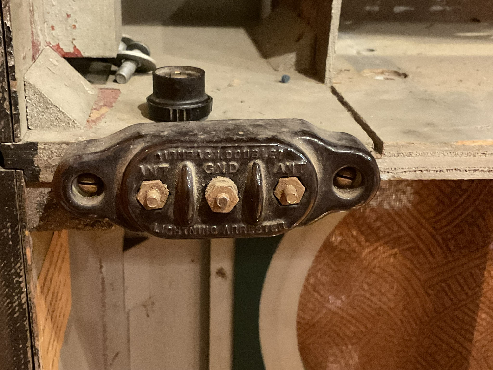
And yes, the chassis had, in fact, two labels, one right on top of the other, advertising the fine phonograph accessory from RCA.
In the realm of hypotheticals (because I'm not at this stage of the work on this radio) is the idea of a switch (definitely a double-pole of some type) that in addition to switching inputs between the RF section and aux input could also disable power to some/most/all of the RF section when in aux input mode practical? This would be as a life-prolonging and energy saving measure, as well as hoping to eliminate a radio signal from being carried over by the activity of the RF section, despite the wired output to the output side also being disconnected by the switch.
I realize that this might not be a period-appropriate modification, but as I'm hoping this will be in frequent, daily use when done, I would like to extend what component life I can and make it more energy efficient, if possible.
Best wishes,
Roy
Posts: 1,797
Threads: 55
Joined: Feb 2015
City: Roseville, MN
Roy,
I've been investigating the double pole double throw situation for switching between radio and Bluetooth for some time. I did it with a tiny AA5 and a tiny transformer to provide power to the BT. But I wanted something more integrated for my Philco 650X and the 37-630 I'll be restoring. So I think I will try disabling the 2-4 MHz band on the sets and use the band switching to disable the rf radio and turn on Bluetooth. That band has nothing on it anyway. Why not liven it up? And when the power supply for Bluetooth comes on it turns on a bright blue LED. I've looked at circuits in AM/FM sets and it appears to favor removing B÷ from one or all of the FM rf stages when switching to AM.
Posts: 18,427
Threads: 622
Joined: Oct 2011
City: Jackson
State, Province, Country: NJ
Roy
Your wife is right (well, she has to be, she's a native speaker), the place names with "-sti" at hte end do not emphasize that last wovel.
Like their capital, București, is pronounced as "Boo-koo-resht' ", the "t" at the end slightly palatalized (softened).
This is why in the rest of the languages, in the spelling of the name of the capital, which is more or less phonetic, "i" is not even present:
Bucharest (English)
Бухарест (Boo-kha-rest - Russian)
Peculiarities of Romanian/Moldavian.
And this is my favorite website for checking pronunciations in all languages, Forvo.
https://forvo.com/search/tiganesti/
I remember I learned the words of Moldavian song, "Melancolie". wsas popular in the old country.
Eu nu mă-ntreb de unde vine, vine,
De unde doru-şi ia izvorul, dorul.
Mă luminez şi-mi pare bine, bine,
Când vine dorul, când dorul vine
Melancolie — dulce melodie,
Melancolie — misterios amor.
Melancolie, melancolie
Din armonia inimii cu dor.
People who do not drink, do not smoke, do not eat red meat will one day feel really stupid lying there and dying from nothing.
Posts: 1,797
Threads: 55
Joined: Feb 2015
City: Roseville, MN
Posts: 5,653
Threads: 56
Joined: Sep 2008
City: Sandwick, BC, CA
Killing radio reception is rather easy, you only need to short the antenna input to ground, this set has no tuned RF amplifier stage, so there isn't a duplicate set of coils to deal with. Another other method would be to switch off the oscillator. In this set it uses a separate detector/AVC tube so you can cut the RF signal there Then again you can usually find a dead spot on the dial, on one of the bands, where nothing is going to interfere with the audio from the Bluetooth.
As Mr Fix points out, and I had forgotten that this era of RCA/CGE sets had this, there is a screw terminal board on the back with a link that cuts the connection between the 6H6 detector/AVC tube, and the 6F5, presumably the switch to engage, disengage the radio was built into the record player attachment, which you can duplicate. Because that phonograph terminal is already there I would not go poking around in the band switch, that is asking for trouble as the switches are complex, and almost unobtainable if you break something, and many of the terminals are not easily accessible, it's just not worth the risk to save a few Watts of electricity. The Australian fellow, Don, of Don't Old Radio shed has added Bluetooth to a number of sets he's worked on, and I think he had it set up to electronically switch in the Bluetooth, I myself would prefer a Part 15 transmitter to broadcast what I want without altering the radio, but there is still enough content on AM around here that I can't be bothered, at least at night.
Regards
Arran
Posts: 172
Threads: 10
Joined: Mar 2026
City: Franklin
State, Province, Country: Maine
Arran,
I have had enough dealings with the band switch in my 37-620 that I have no desire to do so here.
My thought was either a rear-chassis or cabinet-mounted switch solution that in addition to controlling which signal progressed to audio output (like the jumper at the terminal on the back) would also power to the RF section such that it neither, first and foremost, uses up component life in the RF section, nor power if it should sit there and play audio only through the aux port for days. If it's carrying power very far, especially in parallel with signal between said switch and the output section of the radio, I suspect there might need to be some shielded wire used. Again, this is all hypothetical at this point.
And while we're on hypotheticals...
Beside a USB wall adapter, does anyone have thoughts about how to power a USB-connected device inside a radio? This is the Bluetooth receiver I use for streaming to the AM transmitter for now: https://www.amazon.com/dp/B0F1FHV54W
It gets its power from the aforementioned wall adapter, but I'm wondering if there might be some way to power it via the radio's own internal supply. It's USB 2.0, which, if I read correctly provides 5V at a maximum of 500 mA. Since the wall warts and I'm sure their ilk in USB chargers don't play nice with radios, it would be ideal to have something built in and less likely to cause interference.
Keeping period-appropriate is a nice target and is certainly my goal from the traditionally visible faces, but not a requirement when seen from the rear of the case.
Back to troubleshooting in a few minutes.
Best wishes,
Roy
Posts: 172
Threads: 10
Joined: Mar 2026
City: Franklin
State, Province, Country: Maine
In response to MrFixr55's tube-pulling suggestion, here's what I've done so far:
With the 6A8 removed, the 6K7 shows 138.7V on pin 4, as opposed to the 63.5 previously measured and compared to the expected 100.
With the 6K7 removed, the 6A8 shows 107.2V on pin 4, as opposed to the 63.5 previously measured and compared to the expected 100.
With both 6A8 and 6K7 removed, the voltage on the tube-side of C15 and R4 is 218.
The first result seems to be as not good as originally tested, though in the opposite way. The second result seems reasonably close to expected, well-within 20%, but then again, I'm not yet sure how these interact and affect voltages. The reading with both tubes removed is almost twice what is shown on the 6A8 with the 6K7 removed which, if the 6A8 is acting correct, may be expected?
Do we need to check deeper or is there something apparent at this juncture? To my untrained eye, does this suggest that flow is going too easily (maybe not quite a short) through the 6K7 and it's cannibalizing the current?
Best wishes,
Roy
Posts: 18,427
Threads: 622
Joined: Oct 2011
City: Jackson
State, Province, Country: NJ
You could, for the noise reduction reason (wallwart is a DCDC switcher and will be near the radio) try to get a battery powered one (if they exist which I do not know). After all, a cell phone and wireless earbuds for it have exactly that. A battery-powered USB. Which lasts many hours.
People who do not drink, do not smoke, do not eat red meat will one day feel really stupid lying there and dying from nothing.
Posts: 5,653
Threads: 56
Joined: Sep 2008
City: Sandwick, BC, CA
One of the interesting attributes of tube equipment is that no electrons will flow without the tube heaters energized, so if I wanted to shut off the front end of the radio the easiest method would be to shut off the tube heaters. I plan to do this with a Canadian Westinghouse set I have that has a good 6U5 magic eye tube, I'm going to add a small bat switch in one of the existing holes in the chassis, so I can operate the set with the magic eye turned off, you could easily do something similar with this RCA, shut off the tube heaters from the 6H6 on back, which would also save .9 amps of current draw on the heater winding of the power transformer. At the same time you could use the heater winding, which is no longer supplying the front end, to power the Blue Tooth module, and whatever it uses for an audio amp. I'm not certain whether impedance matching will be an issue or not if you feed it into the grid of the 6F5 through the volume control. Since this is a console it may be easier mounting all of this on a panel installed near the back of the cabinet, but remember to twist the heater wires coming out of the chassis, or use a shielded cable for the audio coming out of the module to the phono terminals. The switching is the next problem, one for switching the power from the heaters to the Blue Tooth module, and one for switching the audio between the radio front end, and the Blue Tooth module.
Even with all this added I would still recommend changing the paper caps in the front end of the set, even with the tube heaters shut off there will still be B+ going to the tubes, at various points, but I think you were planning on this anyhow as it's cheap insurance.
Regards
Arran
Posts: 1,797
Threads: 55
Joined: Feb 2015
City: Roseville, MN
Using the power from the set will induce hum and noise interference in the Bluetooth audio. Many have tried and it seems the only solution is to use a 7805 regulator feeding a S0505 isolation module. This isolates the supply ground from BT ground.
Posts: 1,797
Threads: 55
Joined: Feb 2015
City: Roseville, MN
Arran, is it wise to cut off electron flow at the filament or cathode putting, not just plate voltage, but full B+ on the plate of the tube? What will it do when it's switched back?
Users browsing this thread: 7 Guest(s)
|
|
Recent Posts
|
|
under chassis parts locator diagram for 1938 Zenith 9s262
|
| Has anyone gone to the trouble of creating an under chassis parts locator image? Yes, I can identify components by foll...bobloney — 08:57 PM |
|
Plug Voltages Needed For A 1943 CRV-20130 Power Supply
|
| Try looking at this site the book mark is for a old generator that I was given. David https://radionerds.com/index.ph...David — 08:36 PM |
|
Plug Voltages Needed For A 1943 CRV-20130 Power Supply
|
| Hello Everyone,
I am looking for voltage identification for all the pin positions on the socket of a CRV-20130 power su...Tonym4704 — 08:16 PM |
|
Philco P45-6365 Universal Transformer Instruction Manual
|
| Can anyone guide me to where this may be found?GRG — 03:00 PM |
|
54C Complete Teardown/Rebuild
|
| I don't think that I have encountered a 12Z3 before, curious how it uses one of those but includes a #43, which is a 25 ...Arran — 02:17 PM |
|
HiFi (Chifi) tube amp build - but my own design.
|
| It's the other forum. I'm also in DIY, but mostly read there. Honestly, I kinda jumped into this without much thought to...TV MAN — 10:43 AM |
|
Philco 71 Code 125
|
| Hello,
I am in need of a schematic for this radio. Mine has the three separate circular tube shields and a shadow me...dconant — 08:06 AM |
|
Stromberg Carlson 1500 Squeal
|
| And life just keeps getting more complicated.dconant — 07:57 AM |
|
54C Complete Teardown/Rebuild
|
| Hello Roy,
here is this one
sincerely Richardradiorich — 12:45 AM |
|
54C Complete Teardown/Rebuild
|
| Richard,
Had grabbed it already but thank you just the same. I find myself wanting to find some way to block out the...glyphmon — 12:03 AM |
|
Who's Online
|
There are currently 2224 online users. [Complete List]
» 1 Member(s) | 2223 Guest(s)
|
|
|

|
 
|








