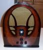
RCA 6K3 Preliminary Capacitor/Resistor Research
Posts: 18,427
Threads: 622
Joined: Oct 2011
City: Jackson
State, Province, Country: NJ
Because 6A7 and 6A8 are the same tube with different sockets, in my experience (and I do not claim to have a lot) I only had one intermittent bad 6A7, but what they are also know to me for is their weak pentode section. Often really weak. To the point that when I needed to replace oe for this exact reason, those that came to me from eBay were pretty much the same.
And I know it was not my tester. Eventually i got one from a guy who promised to test it, and it came as it was supposed to, with over a 1000 test result, wheres mine were anywhere form 150 to 300. Which is, well, very weak.
But I do not remember shorts.
People who do not drink, do not smoke, do not eat red meat will one day feel really stupid lying there and dying from nothing.
Posts: 172
Threads: 10
Joined: Mar 2026
City: Franklin
State, Province, Country: Maine
MrFixr55,
Re: gassy or not, I'm not sure I would be able to tell if it was a glass tube, but I sure as heck can't with the metal ones. After testing according to Rod's suggestion, I will look at ordering at least one 6A8, if not also a 6K7 from Bob Dobush.
Best wishes,
Roy
Posts: 1,797
Threads: 55
Joined: Feb 2015
City: Roseville, MN
Yes, this is very confusing. The voltages go to normal without the 6A8 but any reasoning for the cause of the problem, other than a shorted grid, is beyond me.
Posts: 18,427
Threads: 622
Joined: Oct 2011
City: Jackson
State, Province, Country: NJ
Well, probably not exactly shorted, as the voltage does not drop to real low or zero. But some excessive current probably exists.
People who do not drink, do not smoke, do not eat red meat will one day feel really stupid lying there and dying from nothing.
Posts: 172
Threads: 10
Joined: Mar 2026
City: Franklin
State, Province, Country: Maine
Having removed the screen grid of 6A8 from the circuit while preserving the connections between C15, R4, and the screen grid of the 6K7, there was 200V coming into R4 and 137V leaving it for the screen grid of the 6K7, so substantially similar to the result as with the tube removed (203V and 138V). So, I would say this suggests that the screen grid connection is the culprit.
Just for the H**l of it, after reconnecting the wires to the screen grid pin on the 6A8 socket, I swapped my 6A8GT from the Philco back in to confirm my prior results when testing two weeks ago and still got 173V before R4 and 64V after, to the screen grids respectively, so the two tubes perform similarly.
So again, still confusing to me, if it is in fact a faulty tube that I should wind up with two of them that present in the same way, but this is not a possibility that I'm ruling out. Is there anything external to the tube itself that could cause this unusual current draw, or is it pretty much confined to the internals of the tube itself at this point?
Shall I just order up a spare 6A8 and 6K7 to be safe?
Is the result being the same with or without C15 being connected helpful? What are the implications of that test?
Best wishes,
Roy
Posts: 18,427
Threads: 622
Joined: Oct 2011
City: Jackson
State, Province, Country: NJ
Like I said, I do not think it is a short inside the tube. It looks strange but shorts drop voltage to much lower, closer to zero, values.
The dropout on the resistor might be OK. With the current up to 2.5mA it is allowed for a 50V to drop across that R4. The current is likely smaller.
But the drop at the R4 lower contact....the equivalent of that R14-15-16 bias source is 3.87K.
So 2.5mA would drop no more that 9.7V, which would add to that R4 drop. But it is probably not 2.5mA.
You know what, if it works normallty, maybe it is OK after all.
Let's see...say the SG current is 1mA. It will drop 26V with the tube inserted then altogetther, 22V across R4 and 3.87V after R14 (where it connects to R15).
So. Why did we decide this was a problem, again?
People who do not drink, do not smoke, do not eat red meat will one day feel really stupid lying there and dying from nothing.
Posts: 172
Threads: 10
Joined: Mar 2026
City: Franklin
State, Province, Country: Maine
Mike,
It was of concern because while most of the other voltages were well within the 20% variability stated in the service notes, this one - at first 61V instead of the expected 100V - was a significant outlier.
Again, I don't have a good frame of reference as to what is normal for this period of radios, let alone this specific radio.
Would it be worth trying instead of the 22K value for R4, a smaller value? Would that have implications other than for the screen grids of these two tubes?
Best wishes,
Roy
Posts: 18,427
Threads: 622
Joined: Oct 2011
City: Jackson
State, Province, Country: NJ
I agree 100V or even more dropout across that resistor is too much.
And it seems the 6A8 pulls the current.
I wonder how difficult it is to put a milliammeter in series with the SG of the 6A8 (only this tube, not both of them) and see what current it pulls (it looks almost like it should be 4 - 4.5mA, nd it is excessive).
Probably would not hurt to check the tubes anyway.
People who do not drink, do not smoke, do not eat red meat will one day feel really stupid lying there and dying from nothing.
Posts: 2,327
Threads: 23
Joined: Jul 2020
City: Greenlawn
State, Province, Country: NY
Hi Roy,
One thing about seeing the screen values being closer to published specs with a strong signal. Per the voltage diagram, the measurements are made with the dial around 1000KHz but not receiving a signal and with the antenna disconnected. This will cause no negative AVC voltage, and higher currents (although this is not supposed to happen with a class A amp which at least the IF amp is.
One other possible test would be to measure cathode current. Per both the diagram and the RCA Receiving Tube Manual, the 6A8 cathode current should be 12.3 mA per the schematic, 10.8 per the RCA Receiving Tue Manual (Ver RC14 ca 1940).
For the 6K7 IF stage, the cathode current should be 9.8 mA per the schematic. There is no spec for cathode for the 6K7 in the RCA Receiving Tube Manual (Ver RC14 ca 1940). To measure these currents, the connection between cathode and ground must be broken. This can be done by applying a very thin layer of mylar tape to pin 8 and measuring between the tip of cathode pin (8) and the chassis or socket connection, one tube at a time. this will negate the need of cutting the wire between pin 8 and the chassis.
Remember, that The AVC diode does receive bias from the voltage divider. Verify the correct order and value of those resistors.
You asked about C15. It should be in circuit. Because the screen voltage should be pure DC, there should not be much current drawn by the cap once it charges. Of course, if it us leaky, this could be an issue. Removing C`15 will nit greatly affect Screen voltage and could cause the radio to oscillate, motorboat or use bad language.
There is no statement for cathode, screen or plate current differences based on grid bias. Currents are based on specified grid bias; 0V for both tubes. However, there are statements on transconductance based on grid bias. Normal grid bias for both tubes is 0V. Normal transconductance is listed for normal bias. There is a minimum transconductance listed for negative bias developed by AVC. If I did not post pages from the RCA Receiving Tibe Manual in previous posts to this thread, or if anyone wants them posted again, please let me know. I will be happy to do so.
"Do Justly, love Mercy and walk humbly with your God"- Micah 6:8
"Let us begin to do good"- St. Francis
Best Regards,
MrFixr55
Posts: 5,653
Threads: 56
Joined: Sep 2008
City: Sandwick, BC, CA
Have you taken the 6A8 out of the RCA and tried it in the Philco? Anyhow if you try the 6A8 in the Philco, and the Philco still works, then the tube is likely fine, it may be weak but should still play.
Regards
Arran
Posts: 172
Threads: 10
Joined: Mar 2026
City: Franklin
State, Province, Country: Maine
MrFixr55,
I may try to measure the current using your technique, and also for the screen grid on the the 6A8 as Mike has suggested. I believe my tester can work for this, though I may want to confirm before I try. I think first, just to rule out a problem with the tubes, I will order at least a new 6A8 and 6K7 and try them out first. Maybe I'll be lucky and some oddball problem gets eliminated this way. Worst case scenario, I'll have a couple spare tubes sitting around for a while.
I assumed that C15 needs, long-term, to be included. I take from your statement about its low draw after charging that this means we didn't anticipate much difference in voltage reported with it disconnected vs in-circuit. It is reconnected now and for this most recent batch of test values.
With the voltage dividing resistor, yes, we have verified that the order and size is as specified according to both the schematics and the wiring diagram, R14 = 3500 ohm, R15 = 12500 ohm (closest I could get to 13000), R16 = 82 ohm (closest I could get to 85), R18 = 40 ohm, R17 = 180 ohm (closest I could get to 175).
I believe you did share the tube data sheets for these tubes previously - somewhere on page 5 or 6, I think.
Thank you, everyone, for your continued assistance on this.
Best wishes,
Roy
Posts: 172
Threads: 10
Joined: Mar 2026
City: Franklin
State, Province, Country: Maine
A couple more data points for the night.
I did swap 6A8 tubes between radios again (as Arran suggested) and tested the Philco playing, as well as the RCA. Had both playing side by side for a portion and it was actually quite beautiful sounding. In fact, I think the Philco sounded better with the 6A8 than its own 6A8GT, but it still has some other lingering audio issues, I think in the output section, but that's not for this thread.
I will still pick up a 6A8 and a 6K7 to have for further testing, just to finally rule out the tubes as the issue, and in case I find a need for them in the future.
I have to correct a previous statement of mine - the RCA is, in fact, able to pick up the AM transmitter without the antenna connected. (I think the band switch is a little squirrelly and I may have mistaken the silence in the past for the antenna being disconnected when the problem was really that the band switch was not making proper contact.) In fact, while perhaps not unexpected, the radio seems to have appreciably less hum without an antenna.
In either case, I made a recording of the radio playing Sombr - Back to Friends streamed through the AM transmitter. This is with the volume maybe halfway up. My point to this recording was to get a sense from you fine folks if the sensitivity of the radio seems to be impaired if it can perform this well without an antenna even connected. I'm sure with it connected, the volume wouldn't need to be even this high.
One note regarding the test song, I think it is forgiving when it comes to reproduction on these older radios.
My recording: https://youtu.be/qLV1rEmJRaM
Song used, for comparison: https://www.youtube.com/watch?v=Qvf04YdivnM
Light is off for the test, even though it doesn't make much interference. The dial glass just looks much better this way.
Best wishes,
Roy
(This post was last modified: 05-27-2026, 12:27 AM by glyphmon.)
Posts: 348
Threads: 20
Joined: Nov 2016
City: Cromwell
State, Province, Country: CT
Something I do when I need to measure current when there isn’t a convenient location to measure voltage, is to break the path and install a 1 ohm 2W carbon resistor. The voltage measured across it is the actual current when calculated with ohms law. So .01V is 10 Ma.
Yes it requires a little work, but you’ll have a quick way to test.
I have a small project box inserted between my variac and DUT. It has a receptacle, 1 ohm 25W resistor, and test points across the resistor and receptacle for easy measurements.
Hopefully this is helpful.
Tony
“People may not remember how fast you did a job, but they will remember how well you did it”
Posts: 18,427
Threads: 622
Joined: Oct 2011
City: Jackson
State, Province, Country: NJ
I would say 100 Ohm make it easier. It will give you 0.4V at 4mA. And compared with the 22K resistor it is not much so will not change the Voltage too badly.
People who do not drink, do not smoke, do not eat red meat will one day feel really stupid lying there and dying from nothing.
Posts: 172
Threads: 10
Joined: Mar 2026
City: Franklin
State, Province, Country: Maine
While I am waiting for replacement tubes on the outside chance that it is a tube problem, and not having tested the current as yet, I would like to get an understanding of the path of the flow of electricity in this part of the radio.
My present understanding of this is that we supply the current from the R14/R15 junction (170V specified, tests at 175V). This passes through the R4 resistor to supply the screen grids on the 6A8 and 6K7 tubes. It is also connected via C15 (0.1 mfd) to chassis ground, and the 10 mfd C16 electrolytic.
From my research, in a nutshell, the screen grids regulate the output of the tubes. Aside from a short which as previously mentioned is unlikely, what consumes the power coming into the screen grid? I realize this is getting more into the physics of the operation of the tube than the radio and circuitry itself, but I'm just trying to wrap my head around it.
Based on the connections in this small subsection of the radio, and understanding that these tubes are expecting 100V on the screen grids, is anything else in the radio likely to be affected by the excessive voltage drop right here? It seems to be reasonably isolated. Does it harm the tubes to have lower voltage, or just as before, reduce the output of the tube? If nothing else is likely to be affected, is there any potential harm with trying to change out the resistor for a smaller value that would get the screen grids closer to the 100V mark?
Also, I'm looking at the documents that MrFixr55 supplied about these tubes. Unless I'm reading them wrong, the 6K7 screen current is listed as 1.7 mA with the plate voltage at 250V, and for the 6A8, the screen current is supposed to be 2.7 mA. So, is the total current (hypothetical, according to data sheets) drawn by the two tubes of 1.7 mA and 2.7 mA, or 4.4 mA total, so unexpected?
I may be applying Ohm's law wrong here, but, is it not the case that, with both tubes installed, for example, the roughly 110V drop from one side of the R4 resistor to the other would imply:
current = voltage drop / resistance = 110V / 22K ohms = approx 5 mA
Or am I using the numbers and formula wrong?
Now, I have no idea what might cause the current to vary and by how much, but of course, the radio is supplying approximately 265V to the plate. Does higher plate current necessarily or possibly scale other values in the tube's performance? 265 is 6% higher than 250, and 6% more than 4.4 mA is 4.98, not so far from 5 mA. I'm just guessing here.
I know others have shared some calculations and unfortunately, those are hard for me to follow without seeing where the numbers are coming from.
I suppose at the most basic level, I'm trying to wrap my head around how these values are supposed to work out with the components involved, since everything appears to be correct as far as components are concerned, how do we make the math match what is specified?
Best wishes,
Roy
Users browsing this thread: 1 Guest(s)
|
|
Recent Posts
|
|
under chassis parts locator diagram for 1938 Zenith 9s262
|
| Has anyone gone to the trouble of creating an under chassis parts locator image? Yes, I can identify components by foll...bobloney — 08:57 PM |
|
Plug Voltages Needed For A 1943 CRV-20130 Power Supply
|
| Try looking at this site the book mark is for a old generator that I was given. David https://radionerds.com/index.ph...David — 08:36 PM |
|
Plug Voltages Needed For A 1943 CRV-20130 Power Supply
|
| Hello Everyone,
I am looking for voltage identification for all the pin positions on the socket of a CRV-20130 power su...Tonym4704 — 08:16 PM |
|
Philco P45-6365 Universal Transformer Instruction Manual
|
| Can anyone guide me to where this may be found?GRG — 03:00 PM |
|
54C Complete Teardown/Rebuild
|
| I don't think that I have encountered a 12Z3 before, curious how it uses one of those but includes a #43, which is a 25 ...Arran — 02:17 PM |
|
HiFi (Chifi) tube amp build - but my own design.
|
| It's the other forum. I'm also in DIY, but mostly read there. Honestly, I kinda jumped into this without much thought to...TV MAN — 10:43 AM |
|
Philco 71 Code 125
|
| Hello,
I am in need of a schematic for this radio. Mine has the three separate circular tube shields and a shadow me...dconant — 08:06 AM |
|
Stromberg Carlson 1500 Squeal
|
| And life just keeps getting more complicated.dconant — 07:57 AM |
|
54C Complete Teardown/Rebuild
|
| Hello Roy,
here is this one
sincerely Richardradiorich — 12:45 AM |
|
54C Complete Teardown/Rebuild
|
| Richard,
Had grabbed it already but thank you just the same. I find myself wanting to find some way to block out the...glyphmon — 12:03 AM |
|
Who's Online
|
There are currently 1945 online users. [Complete List]
» 1 Member(s) | 1944 Guest(s)
|
|
|

|
 
|