RCA 6K3 Preliminary Capacitor/Resistor Research
Posts: 18,427
Threads: 622
Joined: Oct 2011
City: Jackson
State, Province, Country: NJ
The voltage divider R14/R15 is first filtered by C10; then this filtered voltage feeds the SG through the resistor R4 that also is filtered by the C15.
Now the question: the Grid 1 of 6A8 (pin 5): what voltage do you have at it? This voltage can be measured right across the R3 (one pin is GND< the other is Grid1).
Should be some -20V.
People who do not drink, do not smoke, do not eat red meat will one day feel really stupid lying there and dying from nothing.
Posts: 172
Threads: 10
Joined: Mar 2026
City: Franklin
State, Province, Country: Maine
Mike,
This one shows -1.7V presently. When I tested it before, it showed -0.4V. This is one of those values marked with an asterisk to say that it can't be accurately measured because of the loading from the meter, but unlike the others, it doesn't show a value for what a meter so connected should read, even if not the true value.
Interestingly, for some reason, right now, without changing any components out, but simply it seems as a result of tuning back and forth and adjusting the volume, the voltage at the R14/15 junction has increased up to approximately 182V. Consequently, my screen grids at 6A8 and 6K7 are now testing at around 90V. Obviously, this gets the screen grids closer, but would this have an adverse impact on C16 or oscillator coil? There's also a connection to the socket of the 6F5, but there's no pin on that position, so I suspect the 6F5 wouldn't care. Not even sure why there's a connection to that pin all by itself.
The rest of the voltages throughout the other tubes seem to be closer to what is specified than they were when tested before, a couple weeks ago, though they weren't very far off to begin with.
I know there is some noise when adjusting the volume, so I'm wondering if some imperfection here might be sabotaging the testing. Even though the 6A8 and 6K7 are in the RF section, the volume and tone controls do have a pretty direct connection to the start (R14) of the voltage dividing resistor - could these be affecting the voltage going into it?
I have some Deoxit D5 and F5 arriving soon. I've seen F5 recommended for volume pots. Maybe trying to clean that up will make a difference.
Best wishes,
Roy
Posts: 18,427
Threads: 622
Joined: Oct 2011
City: Jackson
State, Province, Country: NJ
You can serialize a 1M resistor to your DMM positive probe. Else it stops the oscillation.
It is supposed to oscillate in order to achive some significat neg. volts on that grid.
People who do not drink, do not smoke, do not eat red meat will one day feel really stupid lying there and dying from nothing.
Posts: 172
Threads: 10
Joined: Mar 2026
City: Franklin
State, Province, Country: Maine
Mike,
So with a 1M resistor between probe and pin 5 (Grid 1) I'm showing -4.9V.
Best wishes,
Roy
Posts: 18,427
Threads: 622
Joined: Oct 2011
City: Jackson
State, Province, Country: NJ
Well. Here's the thing.
If your oscillator is oscillating, but not strong enough, your grid voltage is not negative enough, and does not lower the current enough.
The SG shares into that total current and might draw ore than it should.
This could be as simple as a weak oscillator/mixer tube.
When measuring that voltage, try to make sure the oscillator is running (by maybe using another radio). If it is and the grid V is low, that might just be the reason, and them maybe installing a strong tube would cure it.
People who do not drink, do not smoke, do not eat red meat will one day feel really stupid lying there and dying from nothing.
Posts: 172
Threads: 10
Joined: Mar 2026
City: Franklin
State, Province, Country: Maine
Mike,
So to be clear, since the 6A8 is the oscillator tube, then a strong one may address these voltage issues. I will continue with my plan to get a new one from Bob. Just waiting on the Paypal invoice right now.
Best wishes,
Roy
Posts: 18,427
Threads: 622
Joined: Oct 2011
City: Jackson
State, Province, Country: NJ
It might. And even a new one from Bob is not expensive, as 1) it's Bob, 2) it's 6A8, a tube as ubiquitous as could possibly be. I will be surprised if it will exceed $6.
People who do not drink, do not smoke, do not eat red meat will one day feel really stupid lying there and dying from nothing.
Posts: 3,188
Threads: 226
Joined: May 2008
City: Omak
State, Province, Country: WA
Hello Roy,
I have seen a weak 6A8 to cause issues like that too and like mike said they are fairly cheap and a common tube like that is worth having a spare.
Sincerely Richard
Posts: 18,427
Threads: 622
Joined: Oct 2011
City: Jackson
State, Province, Country: NJ
And it should be a new spare. Or even a reference tube for troubleshooting.
People who do not drink, do not smoke, do not eat red meat will one day feel really stupid lying there and dying from nothing.
Posts: 3,188
Threads: 226
Joined: May 2008
City: Omak
State, Province, Country: WA
Hello Mike,
For sure and one of ARF late members would sell tubes I had bought a lot Nos tubes from him .
Sincerely Richard
Posts: 18,427
Threads: 622
Joined: Oct 2011
City: Jackson
State, Province, Country: NJ
I have a reference 6L6, which I bought to check my Hickok 600A for calibration.
Many, I remember, said at the time that those "bogey" tubes are of little use, but I keep it. Costs me little and might come useful one day again.
People who do not drink, do not smoke, do not eat red meat will one day feel really stupid lying there and dying from nothing.
Posts: 172
Threads: 10
Joined: Mar 2026
City: Franklin
State, Province, Country: Maine
New 6A8 (and 6K7, just for good measure) arrived today.
I tested tonight first: with original tubes, and second: with just the 6A8 replaced with the new old stock from Bob Dobush. I'll hold the 6K7 in reserve for now.
Also, in the interim between most recent post and today, I received my Deoxit and used it on the power and band switches (D5), and on the volume control (F5). Magically, the power switch started working again, the volume is much smoother, as is the band switch.
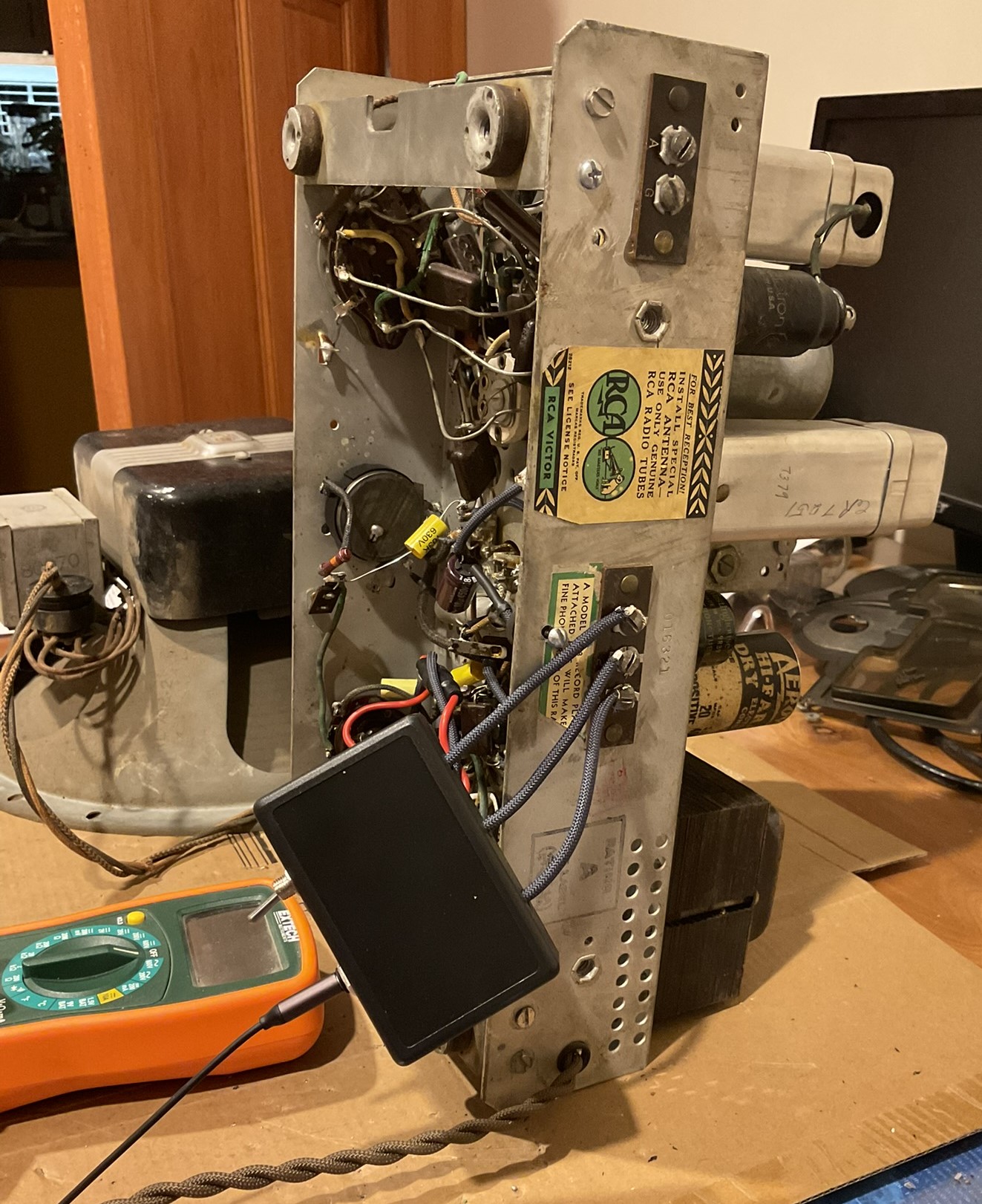
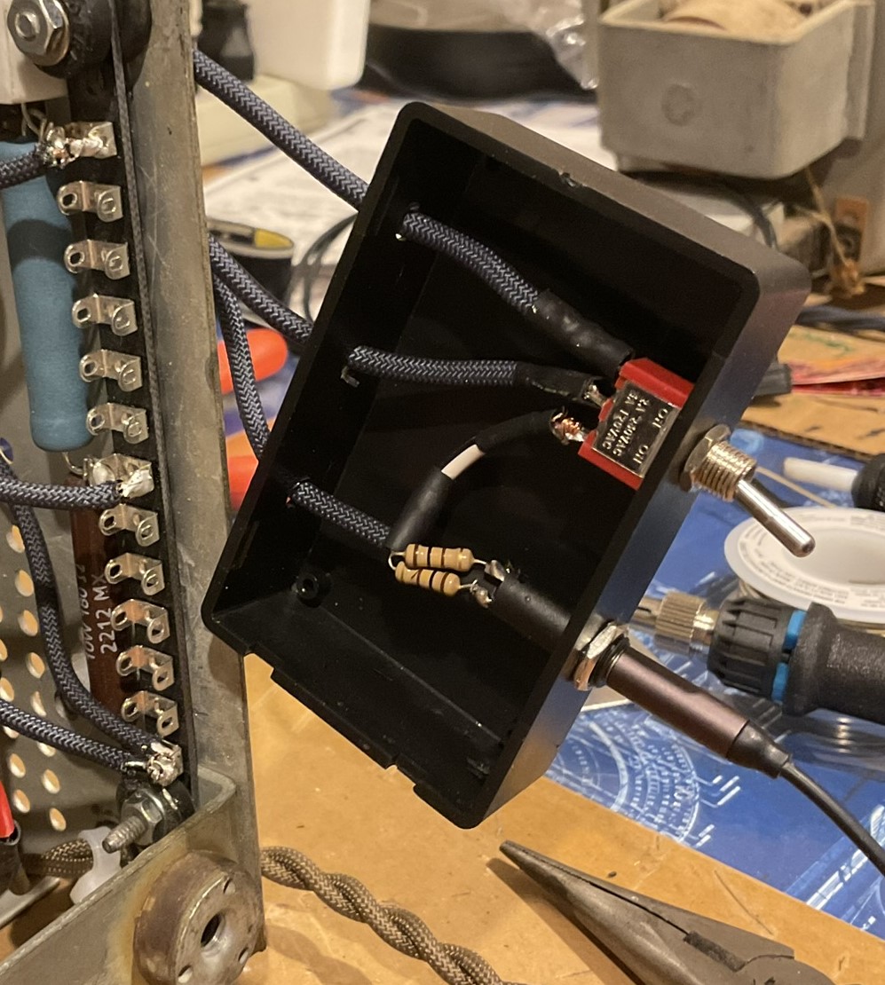
Also, I put in place a switching solution to go between radio and aux input, but this is simply wired to the radio in a removable way, photos below.
With all of these updates in place, my pre-tube swap test was very similar to the last tests:
188V coming off of R14/R15 to R4; 93V on the screen grid pins
After swapping to the replacement 6A8:
189V coming off of R14/R15 to R4; 99.2V on the screen grid pins
To me, this suggests that there might have been some poor switching somewhere that when worked out got us (last time) up from 63V to the 90V area; and second that there may have been some performance issue with the 6A8 that came with the radio that the new tube resolves, getting us up to 99V.
Given that the target for these pins is 100V, I feel like this gets us basically where we're supposed to be in the metric for the screen grids of the 6A8 and 6K7. The radio did seem able to pick up more stations (if not well) than it did before. There are still just a couple local stations, with Boston at about 200 miles away and my antenna solution certainly isn't ideal. Also, my local 1370 AM came in at about 1295, so I'd say it definitely will benefit from an alignment. Timing worked out for me to try Radio Romania International again, and that came in louder and more discernible than before.
My only question now in this phase of troubleshooting is, with 189V coming off of R14/R15 junction, does this bode ill for anything else since it's putting 196V on pin 6 (DP/anode grid)? According to the data sheet for the 6A8, max voltage for that grid is 200 so we're close, but within. Radio documentation specifies 170V. It's obviously also a higher voltage going to the oscillator coil. I double-checked R14 (in-circuit) and it's showing 3.4K (specified 3.5K) so 3% variance - should be well-within tolerance, so I don't think that's the problem.
Aside from this, my next step is to remove the tuning assembly, replace the degraded rubber washers, and clean up the vernier assembly (I'll watch out for any Jesus clips). The tuning knob has been a little stiff since the beginning and the fine-tuning knob just spins (with resistance) without actually adjusting the tuner. I noticed while trying to tune, especially on shortwave, that pressure (not just contact) on the tuning knob/shaft impacts reception, which I suspect may be related to some of the above, even with the new tube.
Photos of the input switch solution which will mount to the cabinet, directly behind the chassis. In this way, there's no modification to the chassis (for this) and is completely removable. It cuts out the output from the RF section beautifully (no bleed through that I can tell yet) and the audio from the aux input is very good quality. I know it's not a period-appropriate switch, but that's not an ultimate concern for me at this point and if it becomes so, I can simply remove it. The cover (removed in the photo showing the interior) will be screwed down to the cabinet and this will snap onto the cover.
Best wishes,
Roy
(This post was last modified: 06-08-2026, 10:02 PM by glyphmon.)
Posts: 18,427
Threads: 622
Joined: Oct 2011
City: Jackson
State, Province, Country: NJ
Your higher voltage could be explained by the meter you use (you use a DMM, right?). The values in teh documentation were likely measured by a 1kOhm/V analog meter.
People who do not drink, do not smoke, do not eat red meat will one day feel really stupid lying there and dying from nothing.
Posts: 172
Threads: 10
Joined: Mar 2026
City: Franklin
State, Province, Country: Maine
Mike,
Given the use of a DMM vs 1kOhm/V analog meter, would it be expected that some points would test to reasonably expected values and others would not?
I take it you wouldn't be concerned about this higher voltage going into pin 6 and the oscillator coil?
Best wishes,
Roy
Posts: 18,427
Threads: 622
Joined: Oct 2011
City: Jackson
State, Province, Country: NJ
There are very few points that would test close on these.
It really depends on the equivalent resistance of the point tested.
One is the rectifier output. A resistance of this tube is in hundreds of Ohms and so the reading is not affected noticeably by the type of the meter used, DMM, VTVM or the old style multimeter.
Also the filament voltages, that are supplied by the transformer directly and range from a 150m to 5A or more in very old radios.
However, once you measure any circuit around the other tubes, this is very different. A plate load is often in single milliamps or even a fraction of such, and the plate load resistance can be 100K (say, a 50K-47nF-50K filter and load create a DC load of 100K) and connecting a 250K-500K to it will affect the load and thus the reading.
The DMM will show the true value, but if you want to go by old schematic-shown values, you also need to use the old multimeter.
This said, once you have experience with these, you can simply judge whether what you see on a DMM looks good or not.
People who do not drink, do not smoke, do not eat red meat will one day feel really stupid lying there and dying from nothing.
Users browsing this thread: 46 Guest(s)
|
|
Recent Posts
|
|
Plug Voltages Needed For A 1943 CRV-20130 Power Supply
|
| hello david,
I have a similar generator in my collection that features a cast iron, single-cylinder Briggs & Stratt...radiorich — 01:00 AM |
|
under chassis parts locator diagram for 1938 Zenith 9s262
|
| Has anyone gone to the trouble of creating an under chassis parts locator image? Yes, I can identify components by foll...bobloney — 08:57 PM |
|
Plug Voltages Needed For A 1943 CRV-20130 Power Supply
|
| Try looking at this site the book mark is for a old generator that I was given. David https://radionerds.com/index.ph...David — 08:36 PM |
|
Plug Voltages Needed For A 1943 CRV-20130 Power Supply
|
| Hello Everyone,
I am looking for voltage identification for all the pin positions on the socket of a CRV-20130 power su...Tonym4704 — 08:16 PM |
|
Philco P45-6365 Universal Transformer Instruction Manual
|
| Can anyone guide me to where this may be found?GRG — 03:00 PM |
|
54C Complete Teardown/Rebuild
|
| I don't think that I have encountered a 12Z3 before, curious how it uses one of those but includes a #43, which is a 25 ...Arran — 02:17 PM |
|
HiFi (Chifi) tube amp build - but my own design.
|
| It's the other forum. I'm also in DIY, but mostly read there. Honestly, I kinda jumped into this without much thought to...TV MAN — 10:43 AM |
|
Philco 71 Code 125
|
| Hello,
I am in need of a schematic for this radio. Mine has the three separate circular tube shields and a shadow me...dconant — 08:06 AM |
|
Stromberg Carlson 1500 Squeal
|
| And life just keeps getting more complicated.dconant — 07:57 AM |
|
54C Complete Teardown/Rebuild
|
| Hello Roy,
here is this one
sincerely Richardradiorich — 12:45 AM |
|
Who's Online
|
There are currently 1916 online users. [Complete List]
» 1 Member(s) | 1915 Guest(s)
|
|
|

|
 
|







