07-27-2026, 09:38 PM
Good evening, folks! As my cabinet restoration has been winding down, I've begun to work on the electric restoration. I think this one will be more a story of resurrection than of restoration. Just like every other radio I find out here in Oklahoma or Kansas, I believe this one has been leasing out to mice in the past!  We'll start out by looking at some photos.
From the front and top, it's not too bad! Dirty, yes, but it'll clean up. It is missing one of the 6V6GT tubes, but that's because I robbed it when my 46-480 needed a new one! The dial will also need to be restrung.
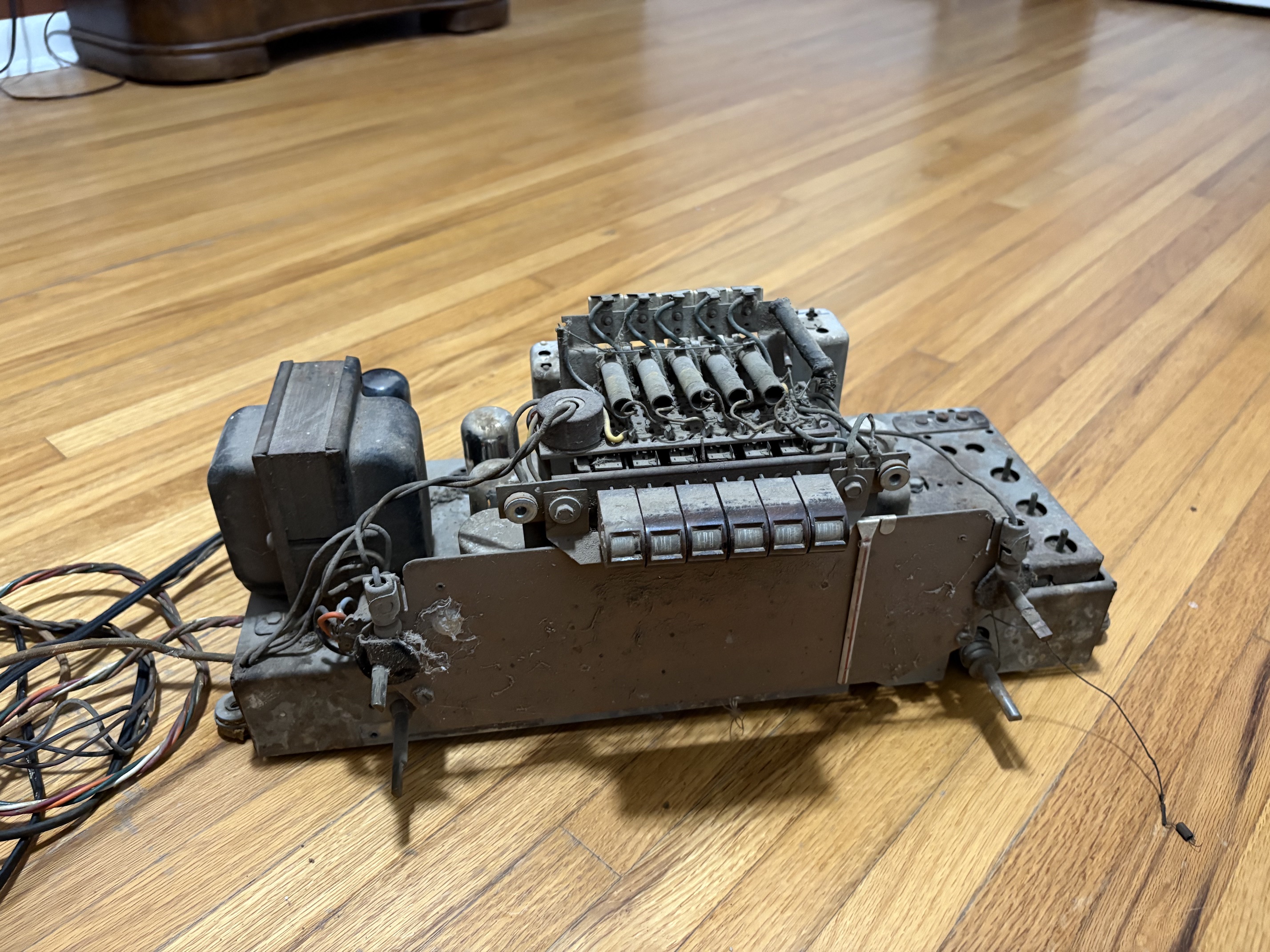
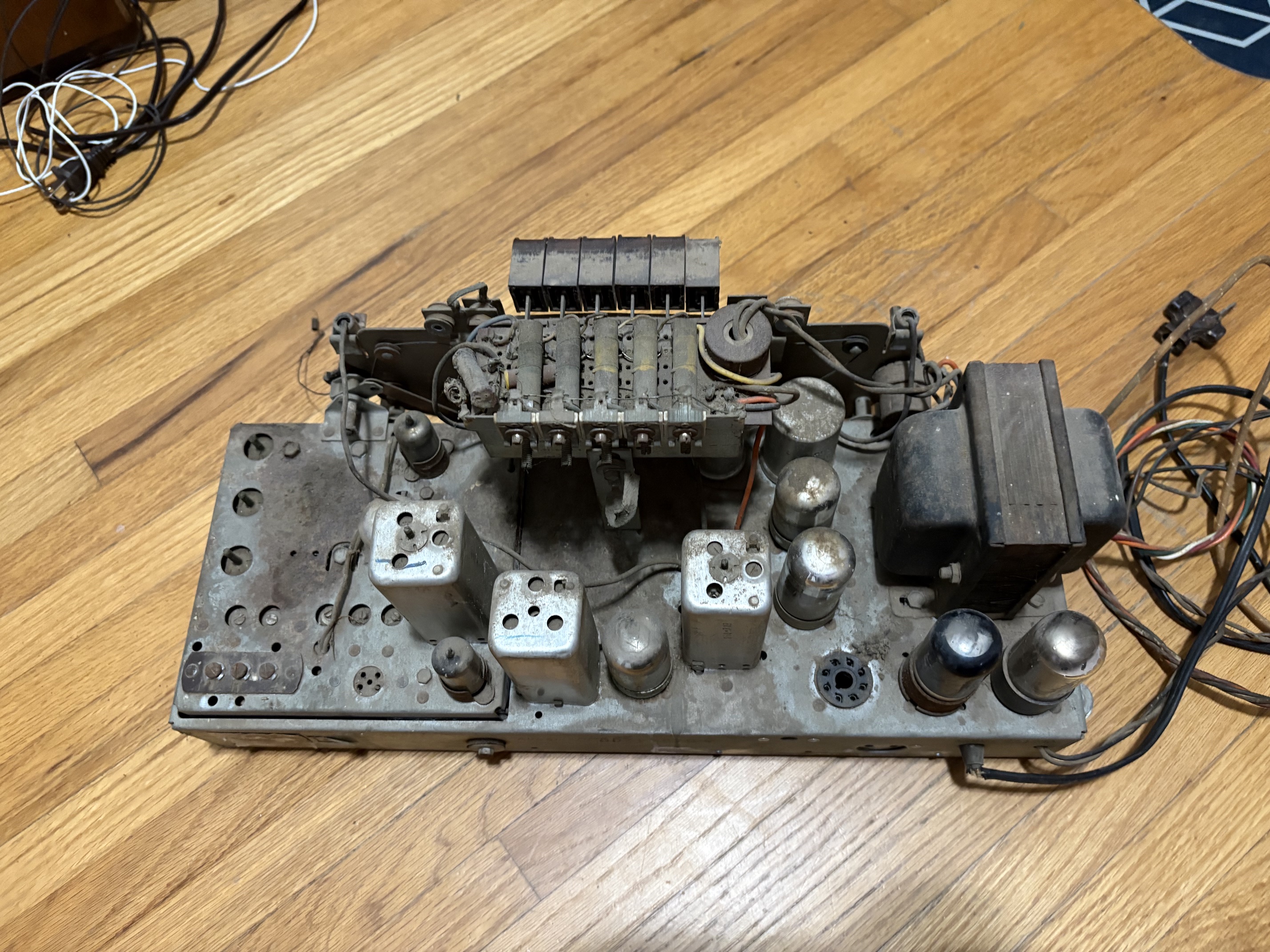
Unlike any of the other Philcos I've worked on, this one has a protective plate covering roughly half of the bottom, on the power supply and audio section.
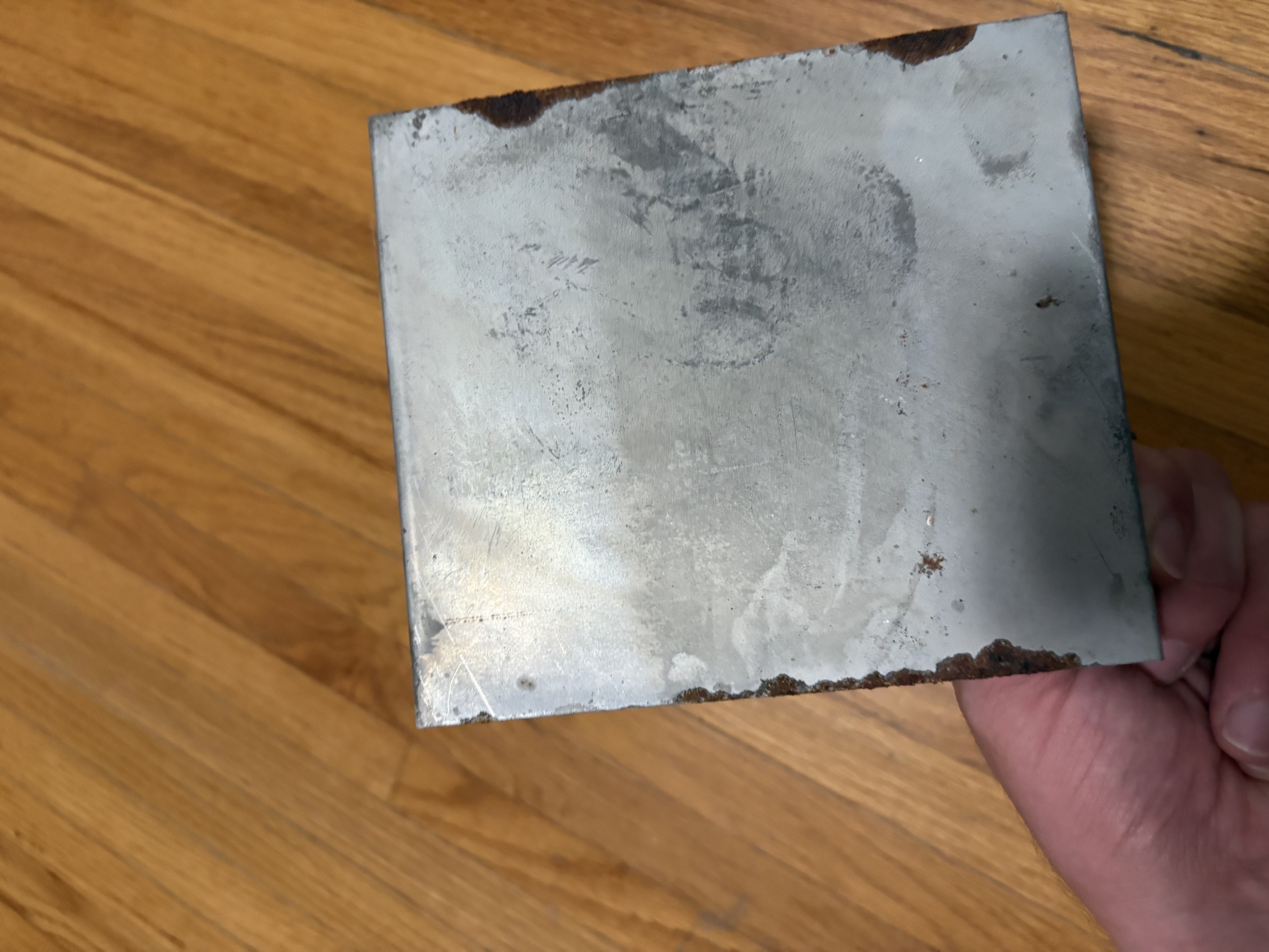
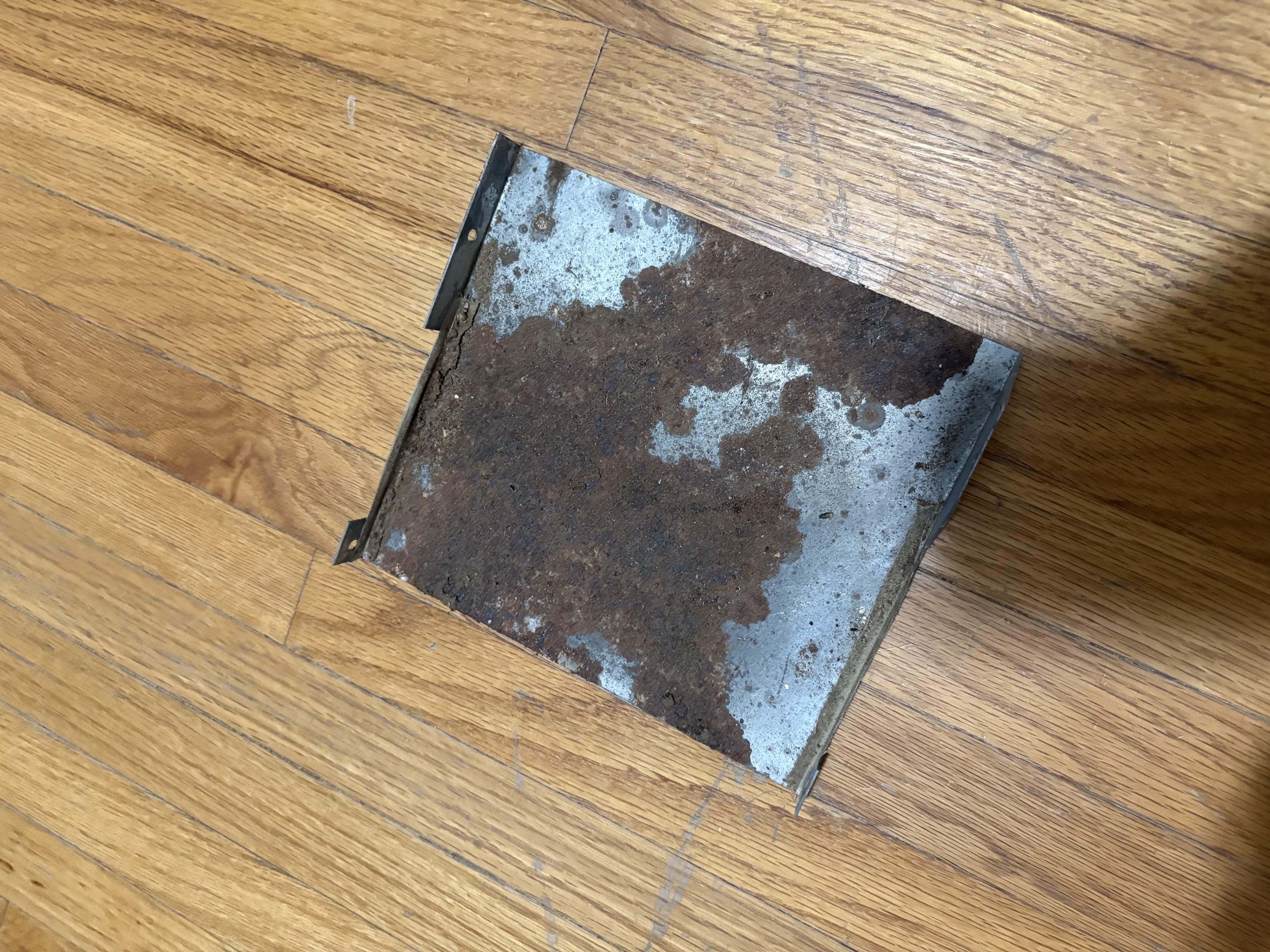
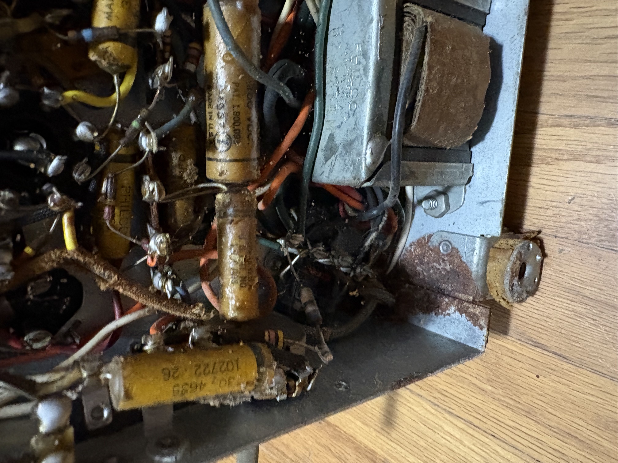
I removed this cover, and that's when I first suspected mice. The inside face of that metal cover was coated in that special rust that only mice can produce. I also notice chewed wire insulation and capacitors.
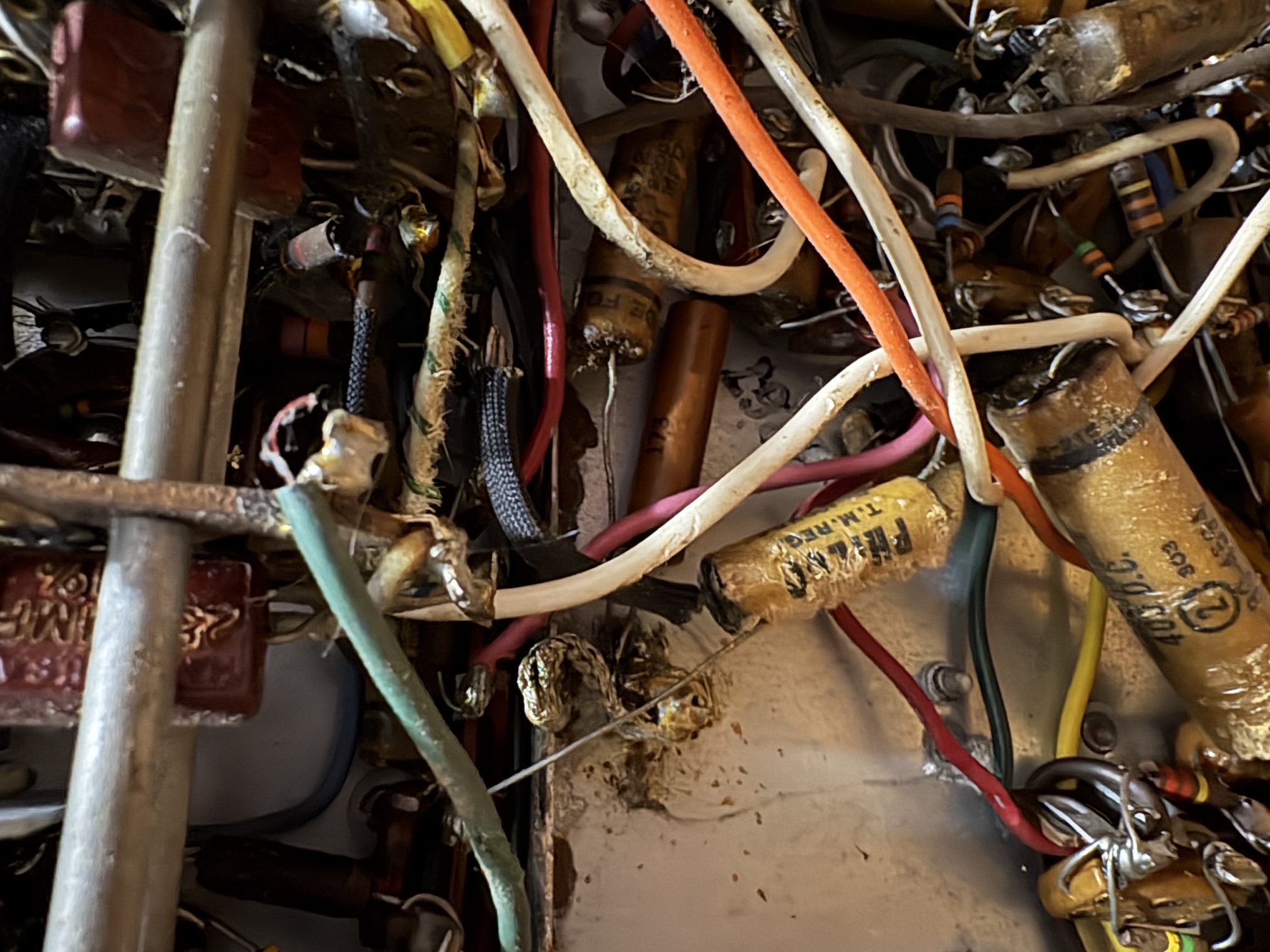
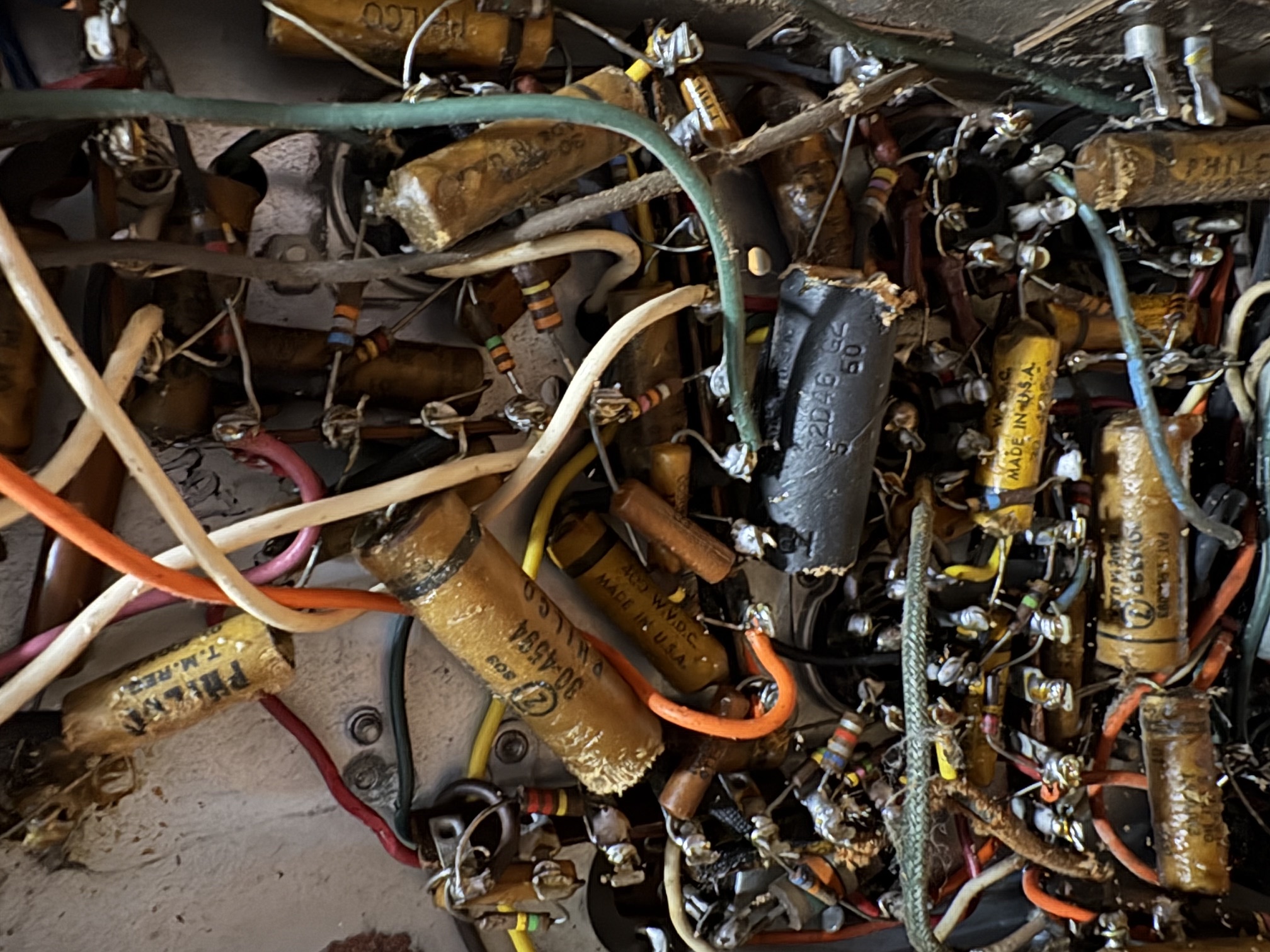
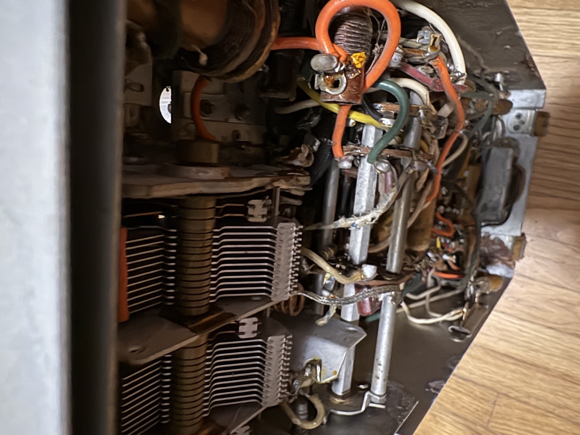
Here's an overall picture of the underside of the chassis, with the metal plate removed to expose the entire interior:
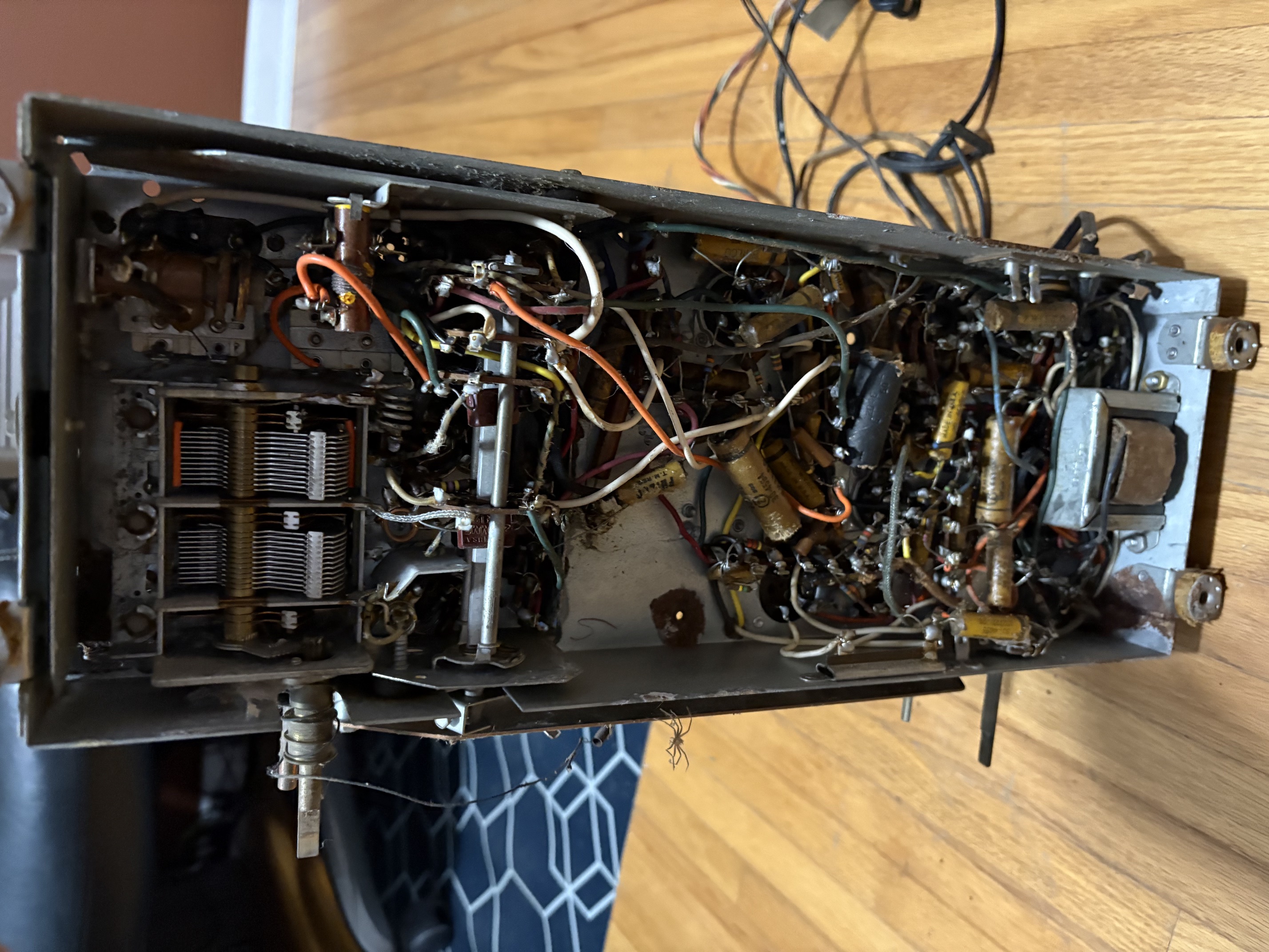
I can use naval jelly to clean up the rust on that removable panel, but I don't know if I'd be able to use it on the interior of the chassis without needing to remove everything. Does anyone else have experience with that? My fear is the rinsing and neutralizing with baking soda; I don't want to soak good components. You can see rusty areas in a few of the other photos, but this corner has a good amount of it, too.
Now I'll move on to talk about recreating the schematic. Y'all probably are used to my process by now, but I always strive to create a fresh, digital copy of the radio's schematic in KiCAD. I always begin by copying from the available Philco schematics, and then I trace through every component and wire in the chassis to make sure there's no errors with the Philco schematic (or any errors I've introduced in copying, both cases happen!). I know some folks here have expressed interest in me producing smaller schematics that are more readable, and I've been thinking about ways to do it. I realized that I can use KiCAD to my advantage, because it allows the draftsman to utilize hierarchical design. That is to say, I can create a "main" drawing composed of blocks representing the various sections of the circuit (power supply, audio output, IF, and RF). This "main" drawing also depicts the buses and signals which interconnect the sections. Then I can create subpages for each of those sections, with flyoffs representing those buses and signals. Each subpage is concise, and contains only the section of the schematic pertaining to that respective portion of the circuit. I've been able to reduce my usual E-size drawing down to five 11" x 17" drawings. Attached is what I have so far, showing the "main" page, the complete power supply page, and part of the audio output page. I'm also attempting to capture all the nominal voltages and test points called out in the original Philco documentation (you can see it in the power supply section, but it's not yet complete in the audio output section.
We'll start out by looking at some photos. From the front and top, it's not too bad! Dirty, yes, but it'll clean up. It is missing one of the 6V6GT tubes, but that's because I robbed it when my 46-480 needed a new one!
The dial will also need to be restrung.Unlike any of the other Philcos I've worked on, this one has a protective plate covering roughly half of the bottom, on the power supply and audio section.
I removed this cover, and that's when I first suspected mice. The inside face of that metal cover was coated in that special rust that only mice can produce. I also notice chewed wire insulation and capacitors.
Here's an overall picture of the underside of the chassis, with the metal plate removed to expose the entire interior:
I can use naval jelly to clean up the rust on that removable panel, but I don't know if I'd be able to use it on the interior of the chassis without needing to remove everything. Does anyone else have experience with that? My fear is the rinsing and neutralizing with baking soda; I don't want to soak good components. You can see rusty areas in a few of the other photos, but this corner has a good amount of it, too.
Now I'll move on to talk about recreating the schematic. Y'all probably are used to my process by now, but I always strive to create a fresh, digital copy of the radio's schematic in KiCAD. I always begin by copying from the available Philco schematics, and then I trace through every component and wire in the chassis to make sure there's no errors with the Philco schematic (or any errors I've introduced in copying, both cases happen!). I know some folks here have expressed interest in me producing smaller schematics that are more readable, and I've been thinking about ways to do it. I realized that I can use KiCAD to my advantage, because it allows the draftsman to utilize hierarchical design. That is to say, I can create a "main" drawing composed of blocks representing the various sections of the circuit (power supply, audio output, IF, and RF). This "main" drawing also depicts the buses and signals which interconnect the sections. Then I can create subpages for each of those sections, with flyoffs representing those buses and signals. Each subpage is concise, and contains only the section of the schematic pertaining to that respective portion of the circuit. I've been able to reduce my usual E-size drawing down to five 11" x 17" drawings. Attached is what I have so far, showing the "main" page, the complete power supply page, and part of the audio output page. I'm also attempting to capture all the nominal voltages and test points called out in the original Philco documentation (you can see it in the power supply section, but it's not yet complete in the audio output section.
Joseph
Philco 39-750 EZ
Philco 46-480
Philco 47-1230
Philco 48-482
Philco 49-906