Posts: 7
Threads: 1
Joined: Aug 2026
City: Mount Airy
State, Province, Country: NC
Hello, I'm new to radio repair & restoration. I really do need some help. My radio is one that my grandfather owned and it has been moving around with us since I don't know when. Unfortunately, some years back I removed all the tubes (don't ask me why - and I also lost them!  ) I see no indication on the chassis that is anything other than code 121.
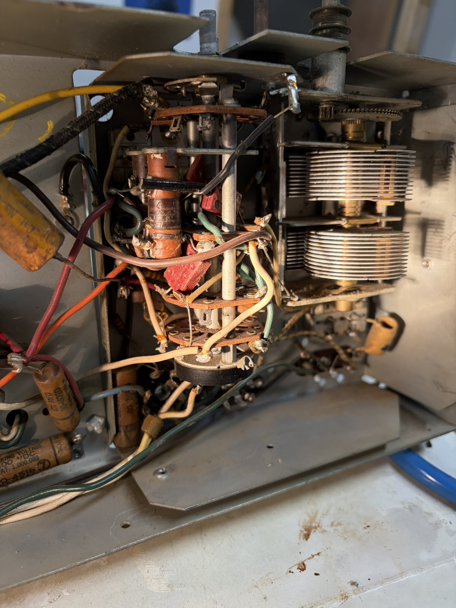
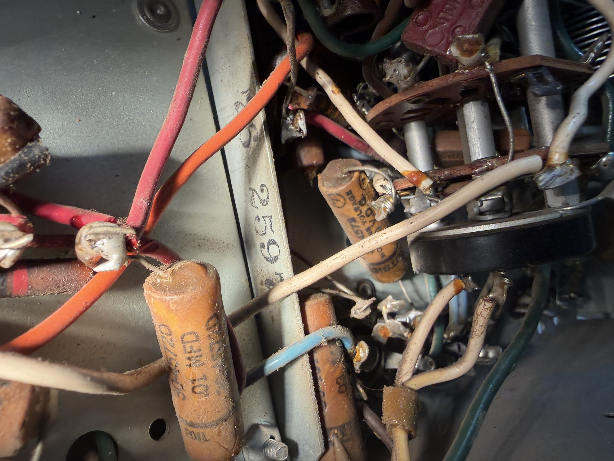
I have been watching a lot of YouTube video's (very helpful by the way). But I really don't find anyone going into any detail on "recaping" this particular chassis. I can see I am in for a long project and I can deal with that. But I am now confronting something I just don't know how to deal with. In the Section 4 of the manual it shows the 7F8 tube and it's resistors and caps. When I look under that tube socket I see it is buried under the selector (I'm sorry I don't know its exact name). But I can't see how I can possibly get to those caps to replace them. I have removed the front and tried loosing the screws that hold up the platform that the selector is a part of. I know there are a couple of resistors right on the back of the socket, so no way I am getting those out. Also there seems to be a capacitor (not really viewable in the picture) that one end seems to be unconnected.
Just wondering if someone could give me an idea on how to approach this? I have a couple of pictures to show the area.
Thanks so much.
Posts: 711
Threads: 46
Joined: Sep 2009
City: Lapeer, MI
State, Province, Country: USA
Welcome to the Phorum! Below is a link to your radio's schematic. It will give you a complete list of components, tube compliment, and location for each tube. I have never worked on this model, but there are many here who can assist.
https://philcoradio.com/library/download...6-1947.pdf
Joe
Courage will follow when Faith takes the lead.
Posts: 7
Threads: 1
Joined: Aug 2026
City: Mount Airy
State, Province, Country: NC
Thanks Joe. Yes one of the first things I did was go to that site and download a schematic. Not the sharpest thing as tubes are hard to read pin out. But it is a good tool for sure. I was hoping someone might have experience with this particular unit might give me a clue how to get to the caps in this particular area. I'm sure I will come up with other questions as well.
I am learning what I will need to get in the way of a safe setup before applying power. So some cost involved as I will need a variac, isolation transformer and I will make the dim bulb tester. Lots of stuff but I will really want to get this old radio to where I can at least listen to AM/FM radio.
Thanks for you input!
Posts: 2,327
Threads: 23
Joined: Jul 2020
City: Greenlawn
State, Province, Country: NY
Hi bsost,
First off, Welcome to the Philco Phorum!! We are glad to have you. We are a "family friendly
Refer to the following link to the schematic and repair instructions for this set:
https://philcoradio.com/library/download...6-1947.pdf
The sub-chassis that you show in the picture is for the convertor (the 7F8 duo-triode) and the 1st IF (the 7H7 remote cutoff pentode). Most of the capacitors on this sub-chassis are mica or silver-mica and (usually) do not require replacement. You need to only worry about paper /foil capacitors. The only 3 paper/ foil capacitors on this sub-chassis are C303 (0.01uF Bypass Cap for B+ for the 1st IF Trans Primary), C304 (0.01uf AVC Bypass for 1st IF Trans Secondary Return) and C305 (0.03uf 1st IF Screen Bypass). Refer to Figure 8 of the above link for location of these caps.
C304 and C305 are relatively easy to get to. Clip the leads as close to the original caps as close as possible. Clean the ends and use the "hook technique" to splice the new caps in. (Bend hooks into the remaining wire and to the leads on the new caps. Squeeze closed, cut off excess and solder.) This will prevent you from having to disturb the tube socket solder joints. Not the prettiest way but the easiest way and is an acceptable method. C303 will be difficult. You may have to loosen and move the band switch. This may prove difficult. You may have to leave C303 in place.
For tube location, refer to the following Nostalgia Air Link:
https://www.nostalgiaair.org/pdfs/Philco...6-1226.pdf
The tube locations are correct but please note that cap and resistor notations are different between the 2 diagrams.
Hope this helps! Keep us posted, we are happy to help you!
"Do Justly, love Mercy and walk humbly with your God"- Micah 6:8
"Let us begin to do good"- St. Francis
Best Regards,
MrFixr55
Posts: 212
Threads: 5
Joined: Sep 2005
City: Newark, Ohio
The 46-1226 receiver is AM/Shortwave only. No FM.
Posts: 7
Threads: 1
Joined: Aug 2026
City: Mount Airy
State, Province, Country: NC
Thanks Ed, couldn't remember that!
Posts: 7
Threads: 1
Joined: Aug 2026
City: Mount Airy
State, Province, Country: NC
Mr Fixr55 wrote:
"Hi bsost,
First off, Welcome to the Philco Phorum!! We are glad to have you. We are a "family friendly
Refer to the following link to the schematic and repair instructions for this set:....."
Thank you so much for this info, EXACTLY what I was needing. I have tried loosening the band switch (I didn't know the name - thank you). I just don't see how to do that. I have seen others here that have completely stripped the chassis. I would prefer not to do that. As for the electrolytics under the metal containers. Any thoughts on whether to rebuild new inside or underneath with new? Thanks again for the details in your post. Will add to my library for this project! 
Posts: 2,327
Threads: 23
Joined: Jul 2020
City: Greenlawn
State, Province, Country: NY
Hi bsost,
There are several folks ( Pholks? After, all, this is the Philco Phorum) who, as a rule, stuff electrolytics with their replacement caps (capacitors). They also hollow out the original paper / foil caps, install the replacement axial Myler caps inside the hollow shell and seal with brown wax, so as to restore the chassis to a museum level of appearance. Several examples can be seen on the Phorum and these are absolutely wonderful!
Whether or not to stuff depends in several factors:
First, is the set sufficiently valuable to perform a "restoration" as opposed to a reconditioning and replacing all the caps and failed resistors with new, modern parts? Sets like these include the highest end Philcos, the Zenith "Stratosphere", EH Scott radios of the early 1930s, Pre-WWII TVs, etc.
Valuable or not, is the set in such outstanding physical condition (chassis completeness, cleanliness, cabinet very clean or if you intend to totally restore the cabinet).
Finally, what do you want to do? Do you want to create a full museum quality restoration because you want to? This is thoroughly OK; I stuffed 2 RCAs because it was easy to do and generally stuff the Bakelite caps on early Philcos because, at the very least, you need to break the connections to the internal components. Procedures for stuffing electrolytic cap cans vary on the mounting and construction of these cans, whether or not they have a paper insulating sleeve (which hudes the "surgery", ease of removal and what tools you have. (A pipe cutter does a nice job.)
There should be room under most Philco chassis to install new electrolytic caps. The new caps are much smaller than the original electrolytics, therefore room can be easily found. Several important things however: - Don't "bridge" the existing capacitor. Early electrolytics tend to short when they dry out. A shorted electrolytic can severely damage the rectifier tube or power transformer or both.
- it is good practice to not have "flying connections", connections between 2 or more components that are merely hanging in the air, unsupported by a terminal. In some cases, the cap can be connected directly to the cathode of the rectifier (input filter) and to whatever tie point for B+ is available (Screen connection for the output tubes, etc.) however, often the capacitor's positive terminal is that tie point. In these cases, one needs to add terminal strips to the chassis. It is ok to either find an existing hole, drill a hole or solder an unused terminal on the strip to the now empty terminal on the capacitor.
- Refer to the attached schematic link from our library. Note that the can (negative terminal) of the 20 uF cap, C20 is not connected to Chassis ground; it connects to the center tap of the hv secondary of the transformer that supplies the HV AC to the rectifier. This center tap is not at ground potential. Since there is a 165 Ohm resistor between the secondary (and the negative terminal of C100) this point is more negative than the chassis ground. This is done to obtain bias (C-) voltages, particularly for the output stage.
This should be a fairly nice sounding set with the cathodyne phase invertor, the push - pull output and the use of negative feedback. The 6K6 (successor to the 41s Philco previously used) are not high output like 6F6s (42s), 6V6s, 2A3s, 6B4s, 6L6s, etc. But nonetheless should put out an honest 5-8 Watts. The phono input can also be used to input an FM tuner, CD player, MP3 player, cable box, guitar, etc., or another turntable using a magnetic cartridge and a preamp.
Good luck with this set!
"Do Justly, love Mercy and walk humbly with your God"- Micah 6:8
"Let us begin to do good"- St. Francis
Best Regards,
MrFixr55
Posts: 7
Threads: 1
Joined: Aug 2026
City: Mount Airy
State, Province, Country: NC
MrFixr55,
Thanks again for your most helpful info! My intention is to get the set working. I really want to just hear the radio play. Most likely I will not use the record player as I would like to install a new model to play multiple rpm's. Idea being I would like to pass this on to my kids/grandkids/great grandkids (yes I have 2 of the latter - I'm old!). I will make sure the set continues to be used and not just left in the basement to rot!
So I'm not sure what my easiest (but most long lasting) solution is. I seriously doubt if anyone is going to be looking "under the hood" to see whether I have stuffed the caps or just put them under the chassis.
I didn't see the link you indicated, "Refer to the attached schematic link from our library". Thanks for directing me to the library though as it has a lot of good info!
Oh I forgot, one more question. I need to change the ac coming in to the 3 prong type of course. Can you direct me to a drawing showing the correct way to do this? Thank you!
(This post was last modified: 08-28-2026, 09:36 AM by bsost.)
Posts: 7
Threads: 1
Joined: Aug 2026
City: Mount Airy
State, Province, Country: NC
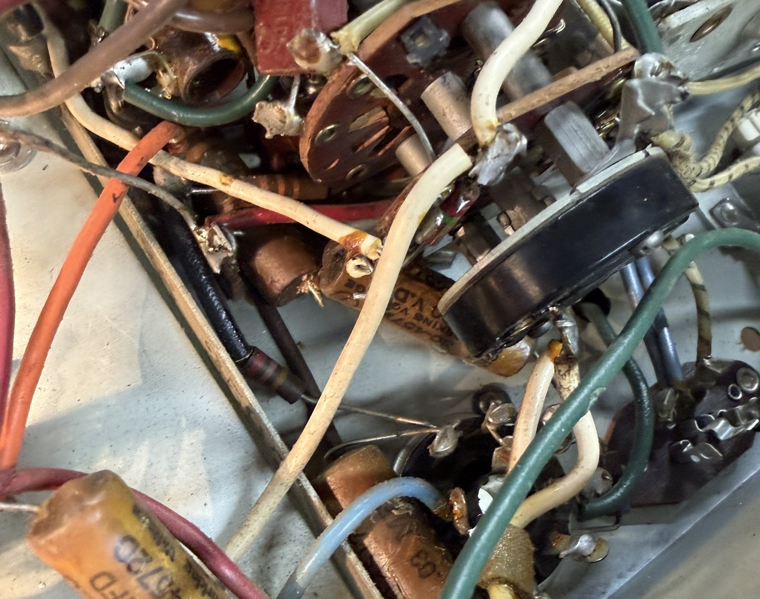
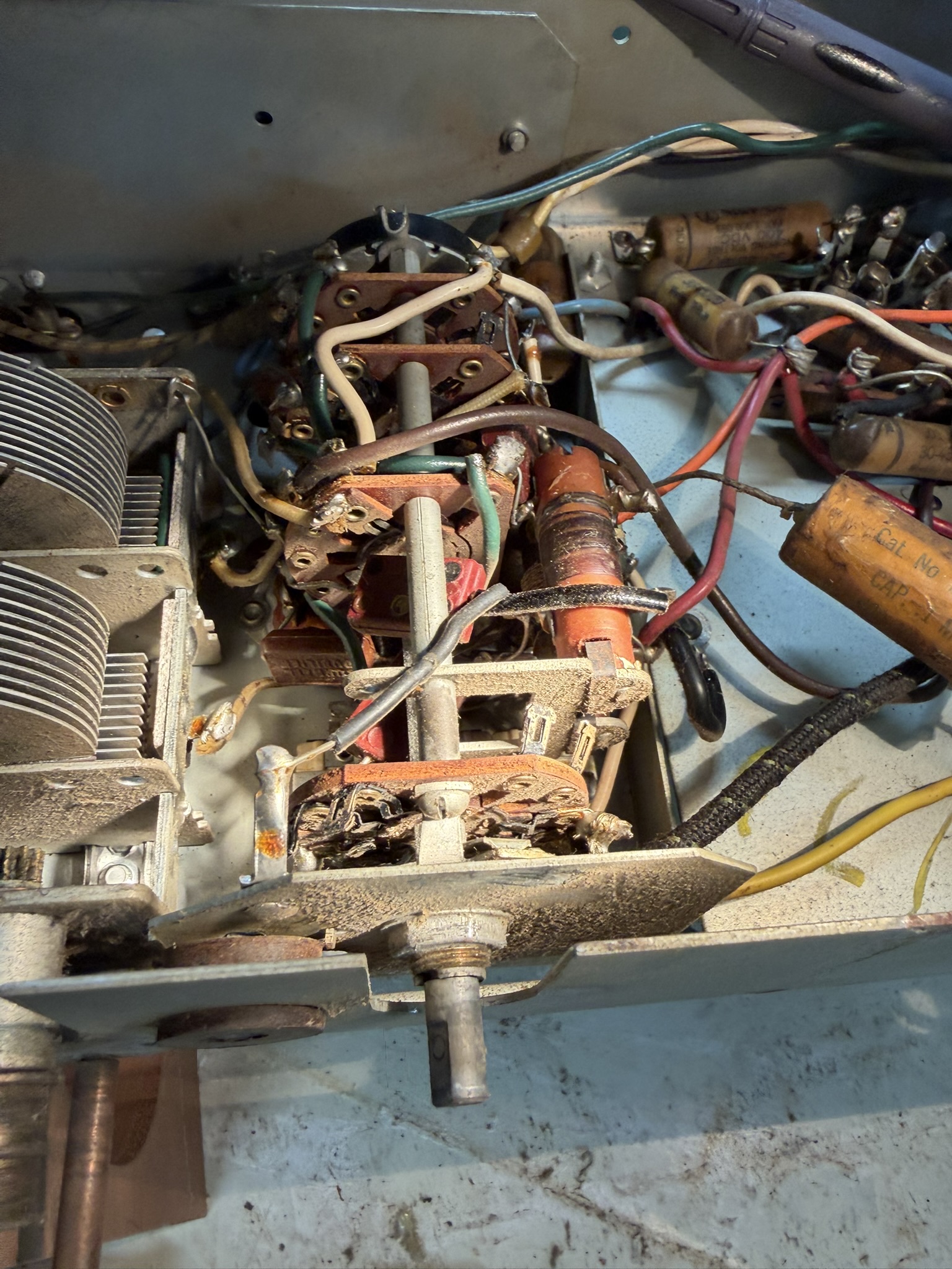
I continue to work on my project but today I am have confronted something that I really don't know how to deal with. I was going to ignore C303 (as MrFixr55 had suggested) but I believe what I have found is a capacitor (maybe C303) that is sitting under the tuner assembly and it has one end not connected to anything (first pic)!
Everything I try I can't get in to see what it should be attached to. Also I have tried to lift up or push down that entire assembly but nothing seems to allow me to do that. Is that nut (second pic) supposed to loosen? I have tried different solvents but nothing seems loosen it. Maybe someone could give me a hint as to how to proceed? I really need to lift up the assembly to see what is going on. Thank you.
(This post was last modified: 08-29-2026, 05:06 PM by bsost.)
Posts: 7
Threads: 1
Joined: Aug 2026
City: Mount Airy
State, Province, Country: NC
MrFixr55,
In your post you wrote, "Refer to the attached schematic link from our library. " I didn't see the link, would you mind posting that? Thank you.
Posts: 434
Threads: 9
Joined: Apr 2023
City: Roanoke
State, Province, Country: Virginia
bsost Wrote: In your post you wrote, "Refer to the attached schematic link from our library. " I didn't see the link, would you mind posting that?
Here at Philco Radio we have the largest online collection of resources for Philco collectors and restorers. It will be worthwhile to become familiar with them. Service resources are in our Service Library. Our Philco Service Index will point you to Service Library resources for any model.
Dale H. Cook, GR/HP/Tek Collector, Roanoke/Lynchburg, VA
https://plymouthcolony.net/starcity/radios/
Users browsing this thread: 1 Guest(s)
|
|
Recent Posts
|
|
Philco 71 Code 125
|
| I noticed on the code 121 schematic the center tap for the 6 volt winding and hv winding are tied together. Is this corr...dconant — 12:16 PM |
|
Philco 45-6365 Universal IFT Instruction Manual
|
| The Philco Parts Catalog for 1942 shows it as usable for 175 kHz, 260 kHz, and 465 kHz. The instructions will show how t...DaleHCook — 11:19 AM |
|
Stromberg Carlson 1500 Squeal
|
| Hello Rob,
I agree with you—I have one here at my house that I need to check out. It’s way over-engineered just to make...radiorich — 11:05 AM |
|
My Atwater Kent 84
|
| Well getting around to restoring my AK84. Mike was a big part in me being able to snatch this one a few years ago. I won...462ron — 10:57 AM |
|
Plug Voltages Needed For A 1943 CRV-20130 Power Supply
|
| The engine is a B&S 23 inch cast Iron holds 2 quarts of oil. The Generator is a 4 pole 1800 rpm mine was made in 195...David — 10:51 AM |
|
Philco 45-6365 Universal IFT Instruction Manual
|
| Dale: Modified topic as suggested. It is not for a specific project. I found it in a box of stuff I recently purchased...GRG — 10:34 AM |
|
Plug Voltages Needed For A 1943 CRV-20130 Power Supply
|
|
That looks a lot like an aircraft connector of some kind ...
That is a MIL-5015 style connector, used in a wide v...DaleHCook — 10:19 AM |
|
Philco P45-6365 Universal Transformer Instruction Manual
|
| I would suggest changing the topic from "P45-6365 Universal Transformer" to "45-6365 Universal IFT."...DaleHCook — 10:08 AM |
|
Stromberg Carlson 1500 Squeal
|
| And life just keeps getting more complicated. By dconant.
Dittos'Jimradio — 08:01 AM |
|
Plug Voltages Needed For A 1943 CRV-20130 Power Supply
|
| That looks a lot like an aircraft connector of some kind, even if it's a U.S.N power supply. I have a book somewhere abo...Arran — 02:56 AM |
|
Who's Online
|
There are currently 2619 online users. [Complete List]
» 1 Member(s) | 2618 Guest(s)
|
|
|

|
 
|








