Restoring Fisher X-101C Integrated Amp
Posts: 348
Threads: 48
Joined: Oct 2013
City: Tioga, Texas, USA
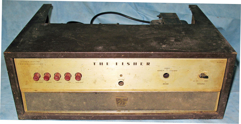
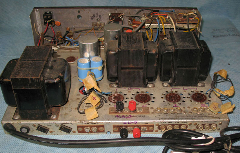
I recently acquired a Fisher X-101C integrated amplifier that had gone through some hacked modifications before I received it. It had served as a roach motel at some period in its lifetime. I have spent hours cleaning both top-side and underneath the chassis. Some of the corrosion they caused underneath will never come off, but I have managed to clean off much of their residue underneath. Top-side I managed to get most of the corrosion to a pretty presentable appearance by using Weiman's metal polish and also Eagle Nevr-Dull polish plus many hours of work. Much of the added wire and components have been removed (much of it was insulated with duct tape). I have been rewiring the chassis as many cables and B+ wires were cut apart and left in place that way. It is a very slow process.
I found a volume control (the type without a switch) to replace the missing Volume control. The Balance control and Mode switch were also missing. I have a new balance control on hand now (they are linear taper, so I was able to find a suitable new manufacture control to use). I will soon get those wired into circuit. The loudness switch tab was broken off, so I have new slide switches to use in replacing all four slide switches. There was too much corrosion on them from the roaches to leave them the way they were.
I have two of the double concentric knobs on order from ebay. Do any of you have spare Fisher P/N E50325-1 knobs? They are the single slender knob that Fisher used with other units such as 400 and 500 series receivers for the on-off volume controls and the tuning knobs. They are ridged on the sides and a brass cap goes on the front. I can get the brass caps, just need the knobs.
Joe
Posts: 13,776
Threads: 580
Joined: Sep 2005
City: Ferdinand
State, Province, Country: Indiana
I just looked at some X-101C photos. The knobs look like the same knobs used on most of the early Fisher solid state receivers. Those pop up on the auction site every now and then...sometimes pricey, sometimes not...
--
Ron Ramirez
Ferdinand IN
Posts: 348
Threads: 48
Joined: Oct 2013
City: Tioga, Texas, USA
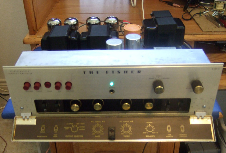
I finished the restoration of the X-101C with the help of Dave Gillespie on the AudioKarma.org site. I performed his EFB modifications as I went along in the restoration.
This poor amp had already seen modifications by a previous owner who only understood enough about electronics to connect things together. It had screen grid mods to the output stages, coupling capacitor values increased by using series parallel values (each one a set of 4 large caps enclosed in duct tape), much duct tape and masking tape, strange wire loops hanging above the chassis, B+ wires and audio cables cut throughout the amp, volume control removed, balance control and mode switch removed etc. Apparently the person was trying to change it into just a power amplifier.
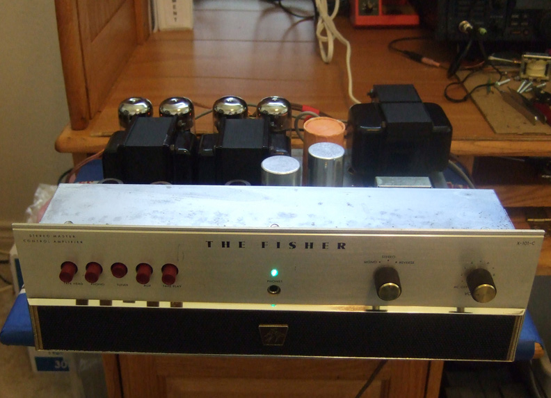
I found replacements for the volume control on ebay, a new balance control, determined how to wire a new make-before-break switch to replace the missing mode switch, removed two added toggle switches. There was extensive corrosion due to being a roach motel for a while both top side and under the chassis. I spent many hours scrubbing and polishing with Weiman's metal polish and Eagle Nevrdull metal polish. Many wires had to be replaced and about 4 audio cables were sacrificed to replace some in the unit that were beyond repair. Most of the rest of the audio cables were repairable and so the original wire color codes were preserved for about 90% of the cabling. New slide switches were installed. RIAA/Tape equalization was deactivated and permanent RIAA equalization applied to both low level inputs, Equalization switch was repurposed as an on/off switch since the volume control I obtained did not have an AC switch on it. The speaker switch was rewired and the missing earphone jack was added. A new 3-pole 3-posn. make before break rotary switch was obtained from Allied Radio and wired to create the mode switch functions and installed. So now most of the original functionality has been restored. A new LV power supply was added that handles Dave Gillespie's EFB modifications that allow B+ variations to cause output tubes screen grids to track any changes and also the negative fixed bias to automatically track B+ changes too. Result is output tubes produce more power with less internal heat dissipation while also reducing distortion. A TL082 Op Amp is added between the preamp stages and the output circuitry allowing the unit to operate as a preamp or a power amplifier as desired. The interconnection point is the old "Reverb In or Out" jacks. The only visible difference externally is a small power transformer top side.
It finally received a new set of tubes and was changed from cathode bias to adjustable grid bias of the output tubes which are now Electro-Harmonix 7591s. Tests showed it produces about 30-32 watts per channel with one channel driven and about 26 to 28 watts with both driven when the output tubes are set to have 30-32mA current per tube. 10 ohm 1/4 watt cathode resistors allow accurate current measurements and also serve to act as a fuse in case a tube shorts. The same is done with the screen grid circuits - a 100 ohm series 1/4 watt resistor protects the output transformers from a shorted tube. I got to test that accidentally when a test probe slipped as I was measuring B+ and one screen grid resistor and cathode resistor immediately went open with a crack sound.
I have been listening to it now for about a week and love the sound.
Joe
Posts: 348
Threads: 48
Joined: Oct 2013
City: Tioga, Texas, USA
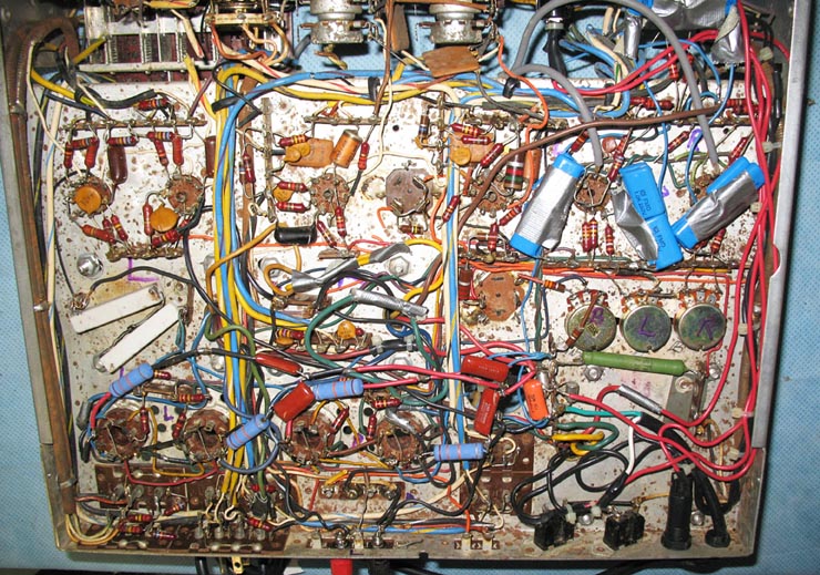
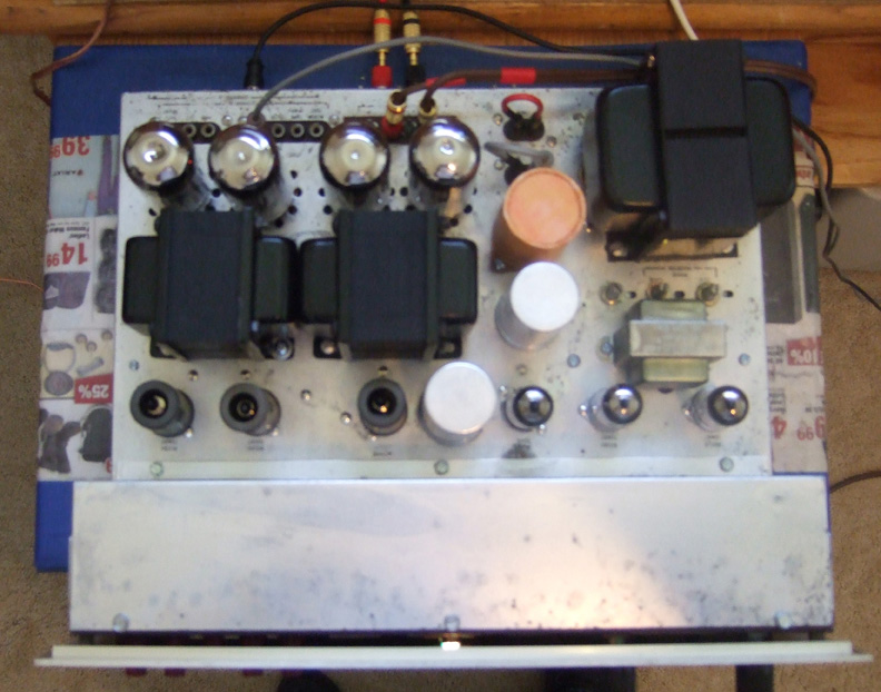
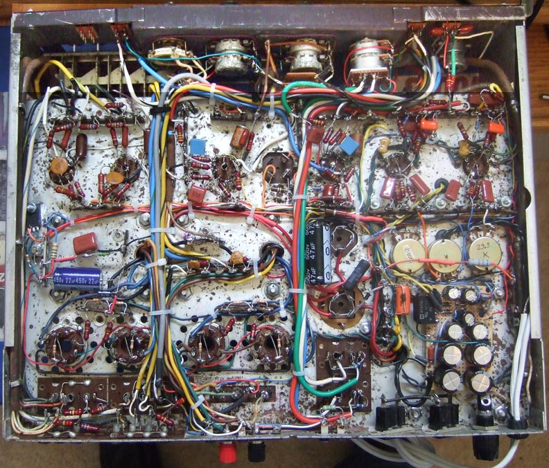
This would not be complete without a few more pictures. One shows under the chassis after repairs and modifications and the other shows the top side with the unit operating.
Joe
Posts: 262
Threads: 27
Joined: Jan 2010
City: Rochester, NY
Excellent Joe!
Hats off
Tim
Posts: 1,475
Threads: 69
Joined: Nov 2012
City: Kansas city, MO.
Really nice job. That certainly was a lot of work but well worth the effort.
Posts: 348
Threads: 48
Joined: Oct 2013
City: Tioga, Texas, USA
One of the interesting parts of the restoration was duplicating the two 200uFd @350V electrolytics in the power supply. I wound up using two can capacitors that are 50uFd X 4 @350V and paralleled them. The one that is above ground potential on the outside metal was about the same size as the original one but I had no insulating sleeve, so I made one using some card stock in a trapezoid shape to wrap the can twice. Once for the inner shorter portion of the top and another to wrap all the way down to the bottom of the outside metal. It was slightly taller than the can height so I could roll the top edge over a circular disc piece of the same card stock. Then I printed a label stating it was 50uFd X 4 configured to make a 200uFd@350VDC. The electrolytics came from Antique Electronic Supply and were ideal for the job. I had one of the bakelite insulation wafers to mount it on the chassis, so I did not have to research that. The end result looks like many OEM insulated caps for voltage doubler power supplies.
One thing I learned about Fisher 500K ohm balance controls is that they are linear taper, not audio taper. Of course the volume control is a 500K ohm audio taper (log taper) control with the loudness tap. I was lucky to find one on ebay, although it did not have an on/off switch. I may eventually try to find a snap switch (also called a micro-switch) with a long straight lever and cut a small slot in the chassis metal, then put custom made brass tab on the control shaft held by a press-on nut that will grab the control shaft and use that to turn the amplifier on. For now a slide switch is handling that task.
The TL082 Op Amp that handles the preamp output is mounted on the back of the balance control. It allows a modification to the driver stage input to prevent Miller effect at the triode grid. It is supplied + and - 11VDC from the LV EFB power supply that also handles DC feeds to the preamp tube heaters plus providing about -50VDC that is used to handle the negative bias adjustment circuit.
Joe
Posts: 344
Threads: 38
Joined: Jun 2011
City: Tustin
State, Province, Country: California
I know this is a couple months old but that 101-C looks great! Dave's EFB and screen mods are great. More power, very stable and they run cooler.
Posts: 348
Threads: 48
Joined: Oct 2013
City: Tioga, Texas, USA
Yes, Dave Gillespie is the expert engineer for Fisher equipment on the internet. I worked with him to develop a complete schematic of his design incorporated into the X-101-C. I included a bill of materials too to help others locate the needed parts for the modifications. The schematic Rev A can be found at AudioKarma.org, http://akdatabase.com/AKview/thumbnails....=17&page=5 as Fisher X-101-C Mods Rev A although I also did a Rev B which has some corrections to the original released document.
I was amazed at how much cooler the output tubes run after being used to the heat produced by older unmodified Fisher amps and receivers. By comparison to my Dynakit Stereo-70, these run cool as cucumbers!
Two other people who were involved in providing modifications to improve Fisher tube audio equipment were Terry Dewick and Drew Bolce. They developed circuitry to provide Individual Bias Adjustment Modification to Fisher sets that use the 7591 and 7868 output tubes. These days it is difficult to find matched quads of those tubes that are truly well matched. The IBAM changes allow each output tube's current to be adjusted to its ideal range for best power output consistent with lowest current, especially when combined with Dave Gillespie's EFB modifications. Dave also advises adding 100 ohm 1/4 watt carbon film resistors in series with each output tube screen grid and using a 10 ohm 1/4 watt resistor to ground for their cathode circuits. It provides some extra protection against an output tube that might short. Both the screen gird and cathode resistors will blow open and act as fuses to protect the output transformers if a short occurs. The 10 ohm cathode resistors make it easy to measure each output tube's current to make sure each is reading equal to its mate in left and right channels.
Based on testing done by Dave Gillespie of the various brands of new tubes on the market, the best results are obtained with Tung-Sol and Electroharmonix tubes with others coming in with somewhat lower power output. The older American made NOS 7591 and 7868 tubes are getting expensive, but do work well and usually better than the new tubes being made now. Eventually they will no longer be available, so the modifications will insure that whatever replacements are available can be made to work at their best potential.
Joe
Posts: 344
Threads: 38
Joined: Jun 2011
City: Tustin
State, Province, Country: California
Very interesting Joe.
Fisher biased most of their amplifiers hot to get the most power out of them. They were well designed though and I've found several with perfectly good original output tubes. I have 4 Fisher amplifiers using 7591's which are my personal favorites. I've done the electrical mods to 2 of them and they run very cool. Wish I had a X-101C as the styling is hard to beat. I do prefer the 6BQ5/7189 amplifiers overall sound but they lack the power I like, even with highly efficient speakers. I have had 2 of the more powerful Fisher stand alone amplifiers. I sold one, a SA300 as I prefer Fisher's 7591 based amps. I use a 400-CX-2 preamp with a stand alone 7591 amplifier which is my favorite set up.
I was fortunate to find quite a few NOS Westinghouse 7591's many years ago. Westinghouse designed the 7591 in 1959 and only Westinghouse and Sylvania produced 7591's in the US. All others are relabeled. I know Toshiba produced them out of the US, and maybe others.
Posts: 348
Threads: 48
Joined: Oct 2013
City: Tioga, Texas, USA
thirtiesradio;
The major downside of the X-101-C is that under the chassis is very crowded. The chassis has very little vertical room since it was apparently designed to be a low profile amplifier. It makes doing very many modifications a challenge. Dave Gillespie worked wonders with this design given the limited space available. I agree that Fisher's 7591 equipped amplifiers sound great and have enough power to handle lower efficiency speakers better than the 6BQ5/7189/EL84 equipped amplifiers. However, for people with limited budgets years ago, the 6BQ5/7591/EL84 amplifiers did a decent job of reproducing the audio spectrum when paired with reasonably priced speakers of the era. My first amplifier was a Heathkit EA-3? a 12 watt mono amplifier using 6BQ5 tubes. I worked in the HS cafeteria to save up money to buy it and put it together. I was proud of the results. That was a learning experience for me as a teenager. I built a number of Heathkits and Dynakits over the years.
Have fun!
Joe
Posts: 2,128
Threads: 18
Joined: Oct 2008
City: Merrick, Long Island, NY
Agree with all. If the Iron is still good, most all of these sets can play on nicely for a long time to come. I've done a few and found that tube sockets were not always the best, so that's something to consider when restoring.
Posts: 344
Threads: 38
Joined: Jun 2011
City: Tustin
State, Province, Country: California
(09-14-2015, 01:36 PM)Joeztech Wrote: thirtiesradio;
The major downside of the X-101-C is that under the chassis is very crowded. The chassis has very little vertical room since it was apparently designed to be a low profile amplifier. It makes doing very many modifications a challenge. Dave Gillespie worked wonders with this design given the limited space available. I agree that Fisher's 7591 equipped amplifiers sound great and have enough power to handle lower efficiency speakers better than the 6BQ5/7189/EL84 equipped amplifiers. However, for people with limited budgets years ago, the 6BQ5/7591/EL84 amplifiers did a decent job of reproducing the audio spectrum when paired with reasonably priced speakers of the era. My first amplifier was a Heathkit EA-3? a 12 watt mono amplifier using 6BQ5 tubes. I worked in the HS cafeteria to save up money to buy it and put it together. I was proud of the results. That was a learning experience for me as a teenager. I built a number of Heathkits and Dynakits over the years.
Have fun!
Joe
Hi Joe,
Yes the X-101-C looks crowded! I think it is Fishers best looking amplifier they ever made. Many others feel that way too as they can get very expensive. Looks like your X-101-C cleaned up great. Nothing nicer than a great looking face plate as Fishers are known to have lettering missing and damage to the finish.
The 6BQ5 heathkit amps are some of the finest sounding. It may have something to do with the simple circuits and their very good output transformers. I've had 2 of them over the years and they both surprised me.
Posts: 344
Threads: 38
Joined: Jun 2011
City: Tustin
State, Province, Country: California
(09-15-2015, 09:48 AM)codefox1 Wrote: Agree with all. If the Iron is still good, most all of these sets can play on nicely for a long time to come. I've done a few and found that tube sockets were not always the best, so that's something to consider when restoring.
I've found the tube sockets to be a problem in several of my Fishers. I just replaced one in an integrated amplifier I rebuilt last month as it had sometime been replaced with a non matching socket. I had to replace 2 of the 9 pin sockets in my X-202-B amplifier as cleaning and pin tightening didn't help. I really cleaned the tube pins as well. It would work well for a month or so after cleaning. Then at start up I'd have a dead channel, and I'd have to wiggle the 2 tubes to get the channel working again.
Users browsing this thread: 1 Guest(s)
|
|
Recent Posts
|
|
Model 80 Antenna Issue?
|
|
I’ve replaced all the caps and resistors and the radio is working but minimal volume unless I put my hand near the re...Hamilton — 08:24 PM |
|
Looking for any info: 1977 Ford-Philco Console Hi-Fi Turntable and Radio
|
| Hi there! this is my first time posting. I recently picked up this Ford-Philco Console record player and radio at a yard...PittsburghToast — 07:28 PM |
|
philco predicta
|
| I found that where I have the 140v B+ there is 50v and the tuner receives 235v through the orange cablecgl18 — 04:14 PM |
|
Philco 91 code 221
|
| Chassis grounds thru rivets is another good place to look. Oh and the stator screws on the tuning cap where the leads at...Radioroslyn — 08:11 AM |
|
Philco 91 code 221
|
| Dirty tube pins and socket, cold solder joint, stray tiny strand of wire, clean the entire area around the oscillator tu...RodB — 08:43 PM |
|
Philco 91 code 221
|
| I have been restoring one of these sets and switched it on yesterday. It didn't exactly spring into life, but after a co...Philconut — 08:26 PM |
|
Philco 50-925 antenna connections
|
| That's super. Glad to hear you figured it out. Paul.Paul Philco322 — 11:11 AM |
|
Philco 50-925 antenna connections
|
| Hello Keith,
great news !!
Sincerely Richardradiorich — 02:14 AM |
|
Philco 50-925 antenna connections
|
| Finally, got the antenna fixed (repaired some broken wires) and have the radio playing. I've got four different schemat...keith49vj3 — 09:38 PM |
|
1949 Motorola 5A9M
|
| Bob, Nice radio. I’ve not seen one before. Keep us updated!Joe Rossi — 07:56 PM |
|
Who's Online
|
There are currently 1338 online users. [Complete List]
» 2 Member(s) | 1336 Guest(s)
|
|
|

|
 
|


![[-] [-]](https://philcoradio.com/phorum/images/bootbb/collapse.png)


