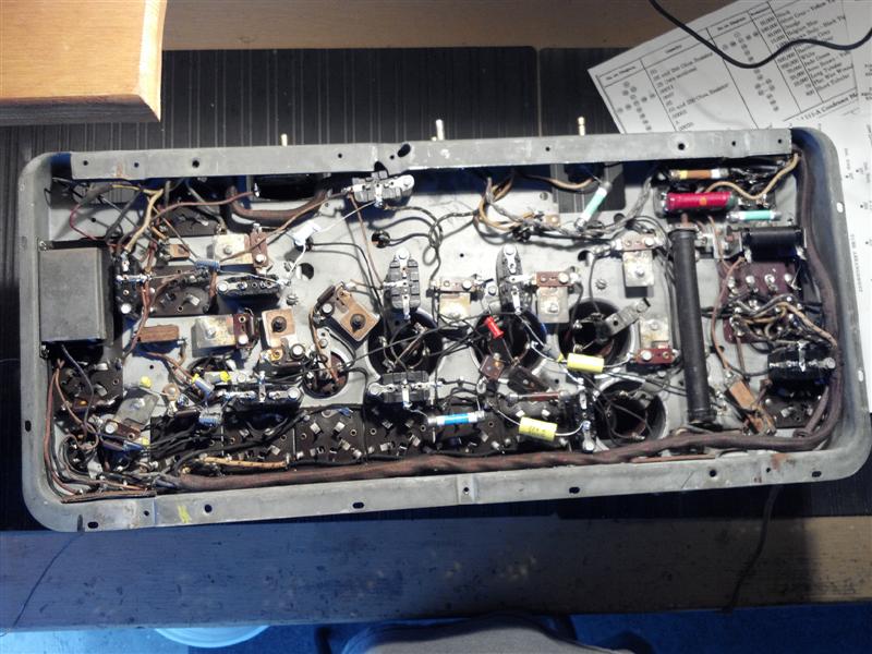
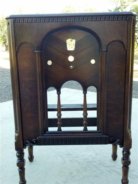
Big HEAVY lots of tubes - for 1931
Posts: 2,353
Threads: 92
Joined: May 2010
City: Clayton, NC
In the Marines we would simply cut off the wounded arm/leg and grow another one.
With respect to the filter can, I chose to disconnect/rebuild/re-connect the wires underneath. Chances are the three resistors there need replacing too.
Way out of tolerance resistors seem to be the standard for these period sets. Most of the ones in my 111 were way out of tolerance too....
Posts: 2,118
Threads: 112
Joined: Jun 2010
City: Medford OR (OR what?)
Recaped and recarbonated:

Need to find the 2 .25mf metal box caps to get rid of those yeller ones.
Otherwise, its tuned up and works great.
OH, the 3 tar buckets in the middle also have 250 ohm wire resistors that do not need to be replaced, if you do not break them taking out the .05mf cap.
The big red dog bone and the 2 black wire wound resistors are the only ones that were in spec, other than the 3 mentioned above. This radio was interesting because Philco was still using their own personal color code for resistors with some odd colors.
(This post was last modified: 08-03-2012, 01:21 AM by Phlogiston.)
Posts: 1,703
Threads: 55
Joined: Sep 2005
City: Evanston, IL
I'm sure you guys have seen my easy, quick method?
BAKELITE BLOCK RE-BUILDING
http://www.philcorepairbench.com/capbuild.htm
Chuck
Posts: 2,118
Threads: 112
Joined: Jun 2010
City: Medford OR (OR what?)
Just hit them with a hammer. That stuff will come out.
Posts: 2,118
Threads: 112
Joined: Jun 2010
City: Medford OR (OR what?)
Oh, and for Jerry - The tone cont has 3 caps in it. The schematic does not say what they are. I used .002mf (3) the tone change is slight, which is the way I like it. I never listen to a radio with the tone turned all the way down. But, I suspect the original values were something like .005mf times 3. Since the tone cont sums up these values that is a total of .015mf.
Also - solder in the short run, med and long in that order so you don't burn the insulation.
Starting on the cabinet now.
(This post was last modified: 08-03-2012, 06:36 PM by Phlogiston.)
Posts: 1,562
Threads: 56
Joined: Nov 2008
City: Sedona, AZ/Placentia/CA
Philogiston, Chucks schematics have the values for the tone control. From left to right, .015, .01 and .01.
Jerry
A friend in need is a pest! Bill Slee ca 1970.
Posts: 2,118
Threads: 112
Joined: Jun 2010
City: Medford OR (OR what?)
First coats of lacquer going on the cabinet now.

Posts: 2,118
Threads: 112
Joined: Jun 2010
City: Medford OR (OR what?)
Posts: 2,353
Threads: 92
Joined: May 2010
City: Clayton, NC
Nice!!  
Like the way you have them displayed. Always looking for better ways to fit more radios in the same space.
Posts: 2,118
Threads: 112
Joined: Jun 2010
City: Medford OR (OR what?)
Yes that cabinet displays 22 radios, though I do not have that many in it (yet), including 2 consoles. It is open in the back above the consoles, so displays in both front and back. I designed and built it and the other 5 matching cabinets. I have space for about 4 more similar ones with the consoles on the bottom. The cabinets are very heavy.
And to answer my own earlier question:
You can stack them at least 4 high.
(This post was last modified: 08-17-2012, 11:42 PM by Phlogiston.)
Posts: 1,562
Threads: 56
Joined: Nov 2008
City: Sedona, AZ/Placentia/CA
Phlog, remember, I can't spell that name. Your pics have helped a lot on the big can. One question please, I have identified and replaced two of the three resistors. The small one, brown/green was cut off of one terminal with the attached wire to sub in a .1 cap. I suspect it was
to replace one of the .5 caps. Could you ID the placement of that resistor so I might have a chance to get the wire attached to the proper location?
Not able to identify the resistor by those colors and both ends off (one came off during recaping from the top side). would love to know which terminal of the power block each end goes to. Moving along slowly.
Edit and add.
OK, after taking out the resistor and looking at it, it is marked as a 150K. Measuring about 170K Schematic says 250K. The resistor although old and associated with the replacement of one of the .5 caps from underneath, doesn't really match the style of the other resistors. The connections were also not looking original. Perhaps someone just grabbed something that might have worked. I put back a 250K resistor. Hope that is right. I now know where it goes underneath after looking at a lot of Chuck's documentation. Onward and forward for the time being. Identifying other resistors underneath, most colors don't match anything I have seen. Working with the schematic I'm almost done tagging them with tape and values. Only one I have not figured out yet, but give me some time.
Jerry
A friend in need is a pest! Bill Slee ca 1970.
(This post was last modified: 08-18-2012, 11:55 PM by jerryhawthorne.)
Posts: 2,353
Threads: 92
Joined: May 2010
City: Clayton, NC
Careful, Philco used their own resistor color code on these early sets.
Users browsing this thread:
|
|
Recent Posts
|
|
Need to purchase some accessories for restoration of my Old Philco Radio
|
| Here is a list of resources found in our online library that you might find useful. Mike's Gobs of Knobs email addres...klondike98 — 01:46 PM |
|
First Radio restoration
|
| Hi Tubeman,
Welcome to the Philco Phorum. Phamily Phriendly Pfun with Phine Pholks Phull of Philco Phacts. (See a p...MrFixr55 — 12:33 PM |
|
First Radio restoration
|
| You could post in the WANTED ADs section here on the Phorum and see if anyone has an RF generator that they want to sell...klondike98 — 11:55 AM |
|
Zenith H725
|
| Good ideas, thank you Arrange and Rich. I have the adhesive aluminum foil already and can try that immediately.
More ...EdHolland — 10:18 AM |
|
Graphics for majestic 1050 dial glass.
|
| Murf;
I found this thread on the ARF, the first photo has a pretty good view of the dial glass.
Regards
ArranArran — 01:12 AM |
|
Zenith H725
|
| hello Ed,
how about that speacial tape used for ducting it's like foil or how about thin piece of
aluminum roof flash...radiorich — 12:19 AM |
|
Zenith H725
|
| Ed;
One material that I have seen, but never tried for this was material for making exhaust gaskets, it's similar to ...Arran — 11:42 PM |
|
Zenith H725
|
| I just remembered, I have some hi temp silicone rubber material which could do the trick. Or a piece of FR4 laminate. Th...EdHolland — 08:39 PM |
|
Zenith H725
|
| The PSU filter cap arrived today (thank you USPS!) so I will work on that later.
Meanwhile, I have the dial, speaker...EdHolland — 06:42 PM |
|
Philco 610B oscillator wiring
|
| Thanks Terry. After checking my notes I think I recorded about -10v at the 6A7 G4/control grid. The screen grid (G3 &...Tubester — 05:59 PM |
|
Who's Online
|
There are currently 1627 online users. [Complete List]
» 2 Member(s) | 1625 Guest(s)
|
|
|

|
 
|


![[-] [-]](https://philcoradio.com/phorum/images/bootbb/collapse.png)


