Posts: 10
Threads: 1
Joined: Oct 2018
City: Thessaloniki
State, Province, Country: Greece
 01-15-2019, 08:19 AM
Hello friends!!! Happy new year!!!
Back in action after a long time...
After replacing 7B7 tube, noise heard but not music

So i started checking DC values... results was not good, but restored. Still no reception... "digging" continued and found something interesting...
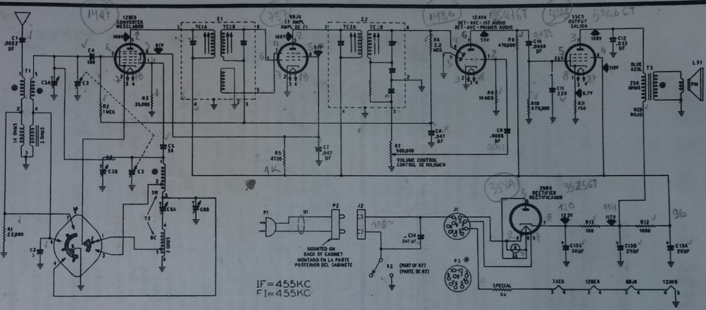
This is an accurate schematic i've found (an old Ron Ramirez's reply) although it is for a different model. The tubes are different but the components values and positions are the same. But...
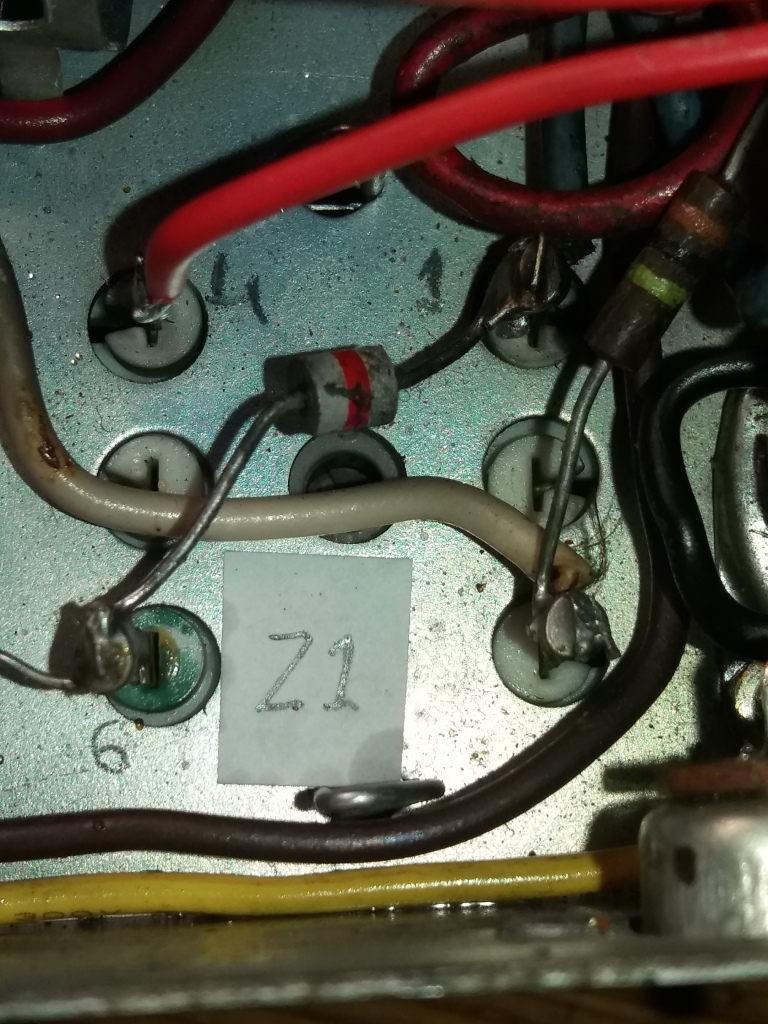
...Z1 transformer seem to have (at the schematic) 5 active pins (1, 3, 4, 5 & 6) although at the radio are only 4 (1, 3, 4 & 6). So pin #4 of 7B7 tube seem to have ...nowhere to connect. Furthermore, this tiny, white component with the red line in the middle, i have no idea what might be...
Thank you in advance!!!
Posts: 7,212
Threads: 266
Joined: Dec 2009
City: Roslyn Pa
Hi,
Do to it's placement it is probably a small value cap (like 2mmfd) although it looks like a small choke but connecting a choke there would be problematic. A small cap would increase the gain but lower the selectivity by adding to the coupling between the two stages.
GL and good DX
de N3GTE
When my pals were reading comic books
I was down in the basement in my dad's
workshop. Perusing his Sam's Photofoacts
Vol 1-50 admiring the old set and trying to
figure out what all those squiggly meant.
Circa 1966
Now I think I've got!
Terry
(This post was last modified: 01-15-2019, 09:59 AM by
Radioroslyn.)
Posts: 10
Threads: 1
Joined: Oct 2018
City: Thessaloniki
State, Province, Country: Greece
Good evening!!!
Indeed Terry, it is a 3pF (or 3mmFd if you preffer) capasitor!!!
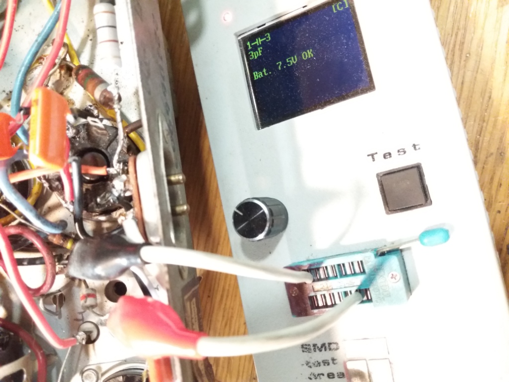
But still haven't found where to connect pin #4 of 7B7 tube.....
So, still searching...
(This post was last modified: 01-18-2019, 04:51 PM by
sv2hwh.)
Posts: 10
Threads: 1
Joined: Oct 2018
City: Thessaloniki
State, Province, Country: Greece
Good morning friends!!!
I'm very happy because, finaly, music heard!!!!!
It seems that this little black wire, twisted on the white one (whitch never found on radio but clearly shown on schematic) is quite critical for the radio to have reception or not.
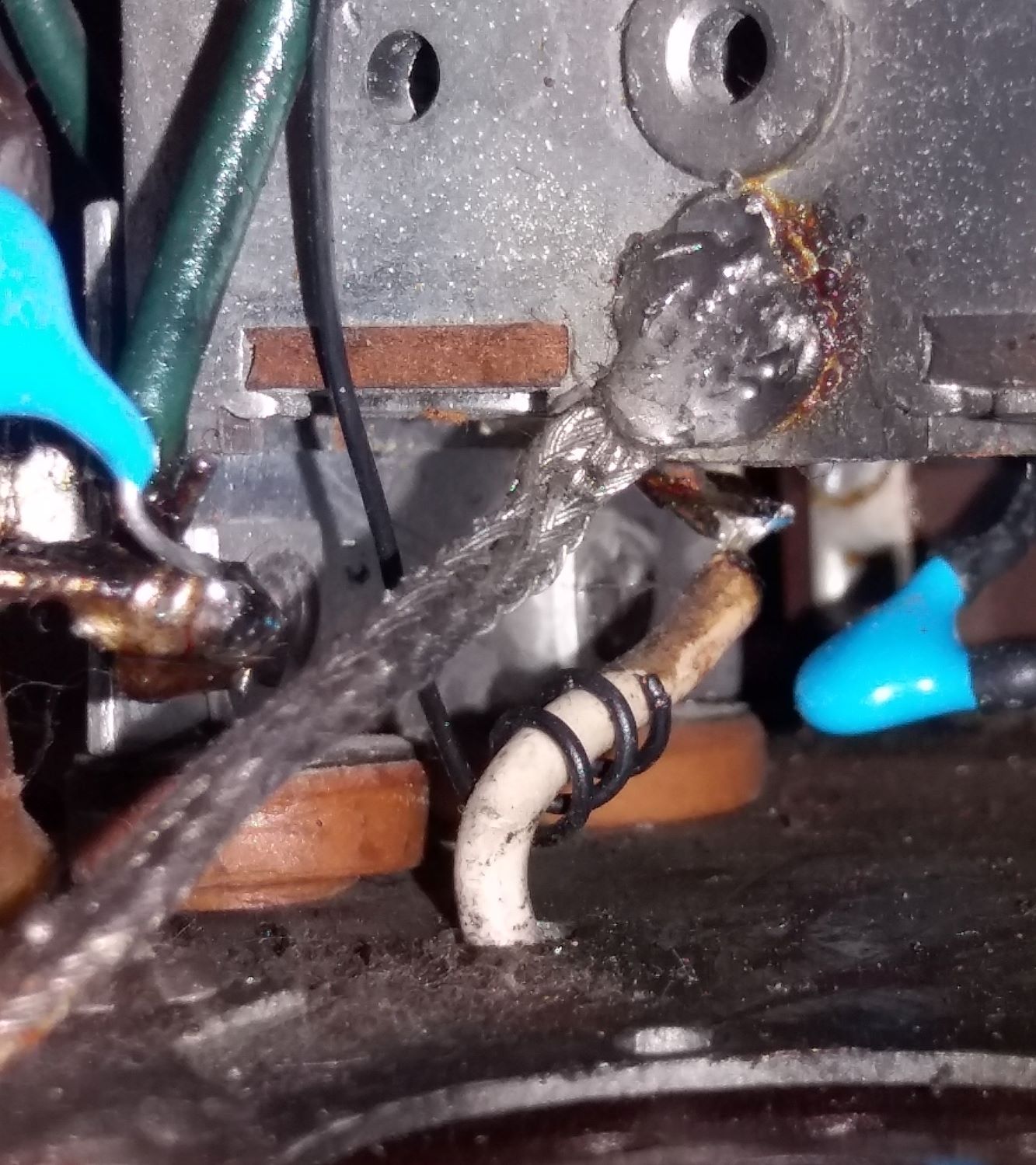
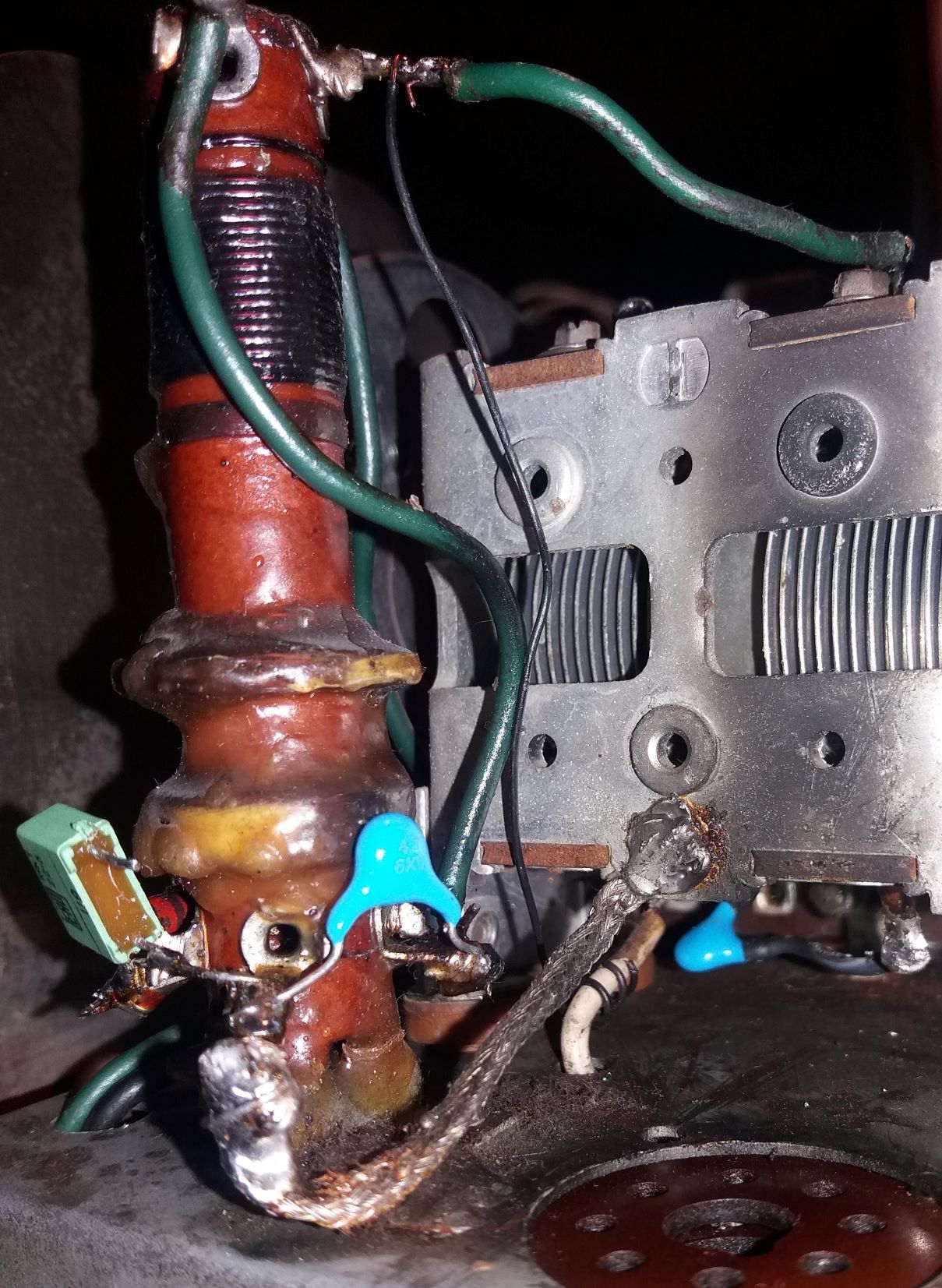
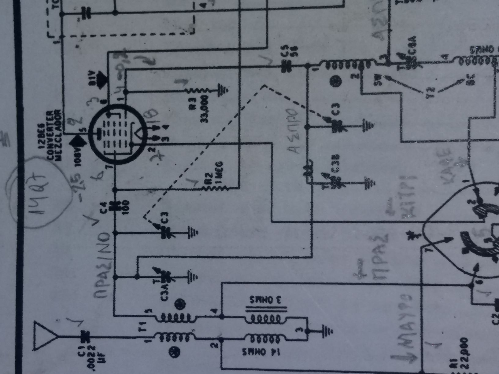
At first i had reception at SW and after a thoroughly cleaning of the selector switch, BC is also at speaker!!!!!!!!
I want to THANK you all for your help!!!!
Have a nice day!!!
Konstantinos, SV2HWH
Posts: 7,212
Threads: 266
Joined: Dec 2009
City: Roslyn Pa
Hi,
Glad to hear you got it sorted out. The wire wrapped the other wire at the ant coil is more than likely used to add so coupling from the oscillator section back in to the amplifier section of the mixer. This evens out the two signals so the signal coming from the ant doesn't overwhelm the osc signal.
GL
When my pals were reading comic books
I was down in the basement in my dad's
workshop. Perusing his Sam's Photofoacts
Vol 1-50 admiring the old set and trying to
figure out what all those squiggly meant.
Circa 1966
Now I think I've got!
Terry
 So i started checking DC values... results was not good, but restored. Still no reception... "digging" continued and found something interesting...


