Posts: 3
Threads: 1
Joined: Mar 2026
City: Pauls Valley
State, Province, Country: OK
Got this Philco 89, and having confusion with it. Two wires are broken on the top side, and no wires going to the dial lamp. One wire goes to the heater of the 44 tube, and one goes to G1 of the 44. Very confusing. Does anyone know where the dial lamp is normally connected?
Posts: 3
Threads: 1
Joined: Mar 2026
City: Pauls Valley
State, Province, Country: OK
I don't know how, but I COMPLETELY spaced out on reading the tube pins. Somehow forgot the orphan pin on a 5 pin socket was #3. All makes sense now. Friggin idiot.
Chris Ingle
Posts: 5,584
Threads: 291
Joined: Nov 2012
City: Wilsonville
State, Province, Country: OR
Welcome to the Phorum!

I saw you posted 3 similar questions so I only approved this one for the thread to continue. If the others had additional info that I missed then just add to this thread with additional questions just as others will try to help you with answers. I also moved the thread to the Electronic Restoration section.
The schematic for the 89 that we have in the library is seen at the following link:
https://philcoradio.com/library/download...l.%201.pdf
The lamp (item 10 on the schematic) looks like it runs directly off the heater/filament transformer. It could be wired in at any one of many places. 6608 lamps are 6v lamps now known as #46 lamps. See:
https://philcoradio.com/library/index.php/parts/lamps/
You mention in one of the posts something about counting pins. Not sure how familiar you are with all this. Tube pins are counted from the "key" (usually a blank space other notation) counter clockwise looking at the bottom of the tube base from under the chassis. So the first pin counter clockwise from the key is 1, then 2 and so on.
Another, perhaps clearer diagram of the 44 tube is here:
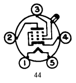
I'm sure others with better trouble shooting skills than I have will chime in on this and help you out.
Posts: 5,584
Threads: 291
Joined: Nov 2012
City: Wilsonville
State, Province, Country: OR
We were both writing at the same time so you answered your own question which is always best! Nevertheless, welcome!
Posts: 3
Threads: 1
Joined: Mar 2026
City: Pauls Valley
State, Province, Country: OK
Is there a chance that anyone rebuilds the antenna coils for a Philco 89? Mine appears to be open, and I can't see a break in the wiring. But I don't see well enough I guess. I get signal at 260Khz aligned all the way thru the rest of the set, but slammed into trouble at the Oscillator alignment step.
The coil in question is the one immediately after the antenna input. I think it is the one marked 2 in the Philco 89 print.
Thanks for the consideration.
Chris I
(This post was last modified: 03-18-2026, 10:40 PM by
ChrisIngle.)
Posts: 18,427
Threads: 622
Joined: Oct 2011
City: Jackson
State, Province, Country: NJ
Judging by what I see on the chassis' picture, it is a 1-layer coil, therefore not many turns.
Try it. It is not too bad. Unless you see really not well enough, these are simpler coil to rewind: no potting, no fancy multy-layer pattern, just two co-axial coils.
People who do not drink, do not smoke, do not eat red meat will one day feel really stupid lying there and dying from nothing.
Posts: 5,584
Threads: 291
Joined: Nov 2012
City: Wilsonville
State, Province, Country: OR
I merged your antenna coil question with the original thread on this 89 to keep all the flow of discussion together, it just makes it easier than having to jump from one thread to another to follow things.
If its the outer winding on the coil that is bad then it should not be too hard to rewind it. Here is a link to an outer coil rewind I did although it is for a 60 antenna coil rather than an 89 and it had a different configuration. Nevertheless the process is similar.
https://philcoradio.com/phorum/showthrea...1#pid86481








