Modified 54C - Oscillator Issue
Posts: 13,776
Threads: 580
Joined: Sep 2005
City: Ferdinand
State, Province, Country: Indiana
Just for fun, I decided to try and see if I could convert a 54C to use octal tubes in order to eliminate the two large dropping resistors. It was mostly successful.
Mostly?
Well, now the thing will not tune correctly. The oscillator is working, but is way, way out of range - beyond a simple alignment issue.
Our local AM station at 990 kc won't even come in. Stations which should be on the higher end of the band are coming in on the lower end.
IFs are properly aligned at 460 kc.
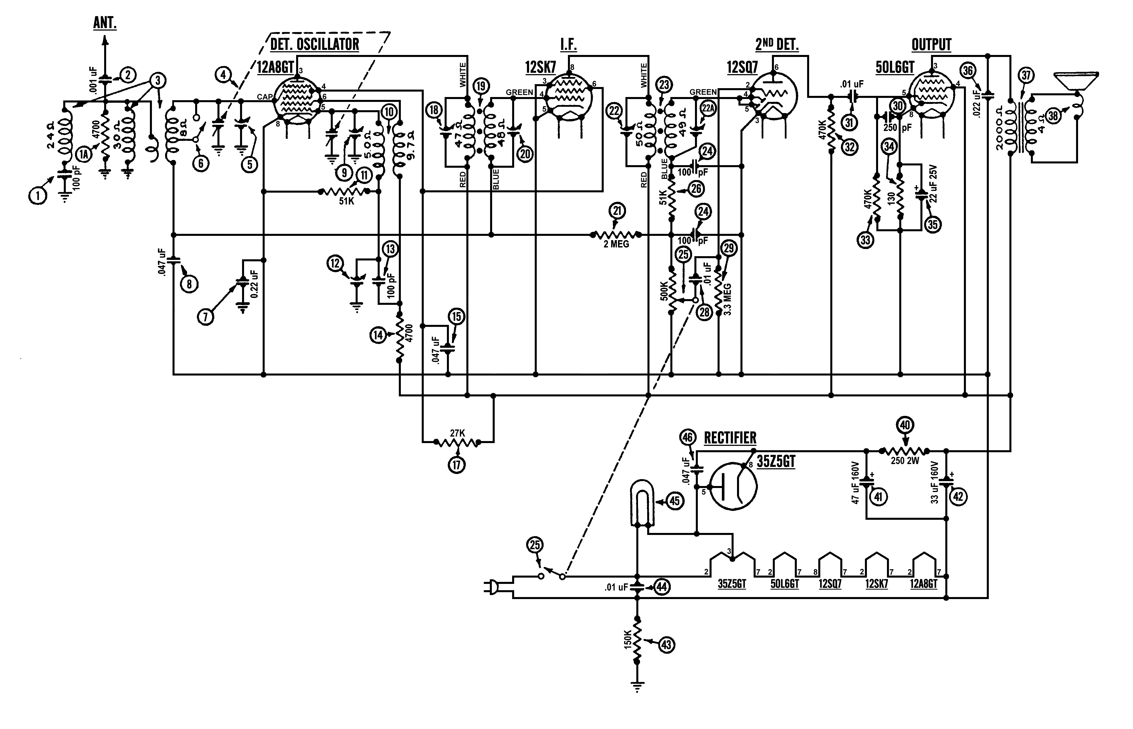
Please look over the modified schematic below, and then tell me -
Would you consider this to be an oscillator coil issue? Or is there something else I am missing here?
Thanks. Oh, and you can compare the schematic below with the original 54 schematic which may be found here.

--
Ron Ramirez
Ferdinand IN
Posts: 1,411
Threads: 71
Joined: Oct 2007
City: Linn Creek, MO
Did the radio align properly before the modification? One would not expect the characteristics of the 12A8GT to be much different than the 6A7. Could capacitor number 13 be bad. You might try adding a cap parallel with 12 and 13. May have to add a couple of turns to the primary of the coil.
Steve
M R Radios C M Tubes
Posts: 13,776
Threads: 580
Joined: Sep 2005
City: Ferdinand
State, Province, Country: Indiana
Steve,
Thank you for responding.
I did not attempt to operate the radio in its "as is" state. It had been "restored" by someone but they did a very poor, sloppy job and I opted to not even try it.
I have done this octal conversion before, on a 38-14, and had no issues whatsoever.
Just for fun, I tried different capacitors in parallel with the oscillator section of the tuning capacitor. Using a 150 pF put me in the ballpark as far as getting the tracking correct is concerned. 180pF also worked but was a bit too much. This is why I was thinking perhaps something about the oscillator coil's characteristics has changed.
I'm baking the oscillator coil now, and I may try a different 12A8GT. I currently have a tested used tube in that socket. i do have a few NOS 12A8GTs. As you say, the characteristics of both it and the 6A7 are very similar.
--
Ron Ramirez
Ferdinand IN
Posts: 285
Threads: 27
Joined: Nov 2012
City: Tehachapi. California
Ron
All things being equal. Sounds like the inter electrode capacitance is less than the 6A7 making it oscillate faster. You might try to measure the capacitance between the elements of the two tubes and then add some extra capacitance to slow it down.
!!!!!!!!!!!!!!!!!!!RESISTANCE IS FUTILE!!!!!!!!!!!!!!!!!!!!!!
/\/\/\/\/\/\/\/\/\
[Image: http://philcoradio.com/phorum/images/smi...on_eek.gif] Chris
Posts: 285
Threads: 27
Joined: Nov 2012
City: Tehachapi. California
I see the valve museum says that they are the same except for the heater voltage. Sounds like you are right it should work. Time for tube swapping?
!!!!!!!!!!!!!!!!!!!RESISTANCE IS FUTILE!!!!!!!!!!!!!!!!!!!!!!
/\/\/\/\/\/\/\/\/\
[Image: http://philcoradio.com/phorum/images/smi...on_eek.gif] Chris
Posts: 1,266
Threads: 11
Joined: Jul 2020
City: Greenlawn
State, Province, Country: NY
Hi Ron,
If I am reading the schematic right (And that may be an issue, as I am fighting either a bug or the effects of the COVID Vax Booster), it appears that you eliminated the cathode bias resistor. (Maybe resistance really is futile??  ) Try putting it back in. Both units use a voltage divider in the B- Return to create an ersatz "C-" supply, but there is more resistance in the 38-18 than the 54.
Hope this helps.
"Do Justly, love Mercy and walk humbly with your God"- Micah 6:8
"Let us begin to do good"- St. Francis
Best Regards,
MrFixr55
Posts: 13,776
Threads: 580
Joined: Sep 2005
City: Ferdinand
State, Province, Country: Indiana
Great catch, MrFixr, thanks. I'll take care of that.
--
Ron Ramirez
Ferdinand IN
Posts: 16,533
Threads: 573
Joined: Oct 2011
City: Jackson
State, Province, Country: NJ
As someone here said "all things being equal", your IF being aligned, the sole person who could shift things is Mr. Oscillator.
If you kept the resonant elements from the earlier sch, then my bet would be on the parasitics of the tube (the IE capacitance).
I would start from measuring the output frequency of the Oscilaltor at the start and the end of the scale; and then possibly (if you have the old 54C) comparing it to the current one.
People who do not drink, do not smoke, do not eat red meat will one day feel really stupid lying there and dying from nothing.
Posts: 13,776
Threads: 580
Joined: Sep 2005
City: Ferdinand
State, Province, Country: Indiana
The inter-electrode capacitance of the oscillator "plate" grid (G2) and the oscillator grid (G1) are very, very close between the 6A7 and the 12A8GT.
And MrFixr, after thinking, I realized that if the 12A8GT needed more cathode bias, I don't think it would affect the oscillator frequency that much - the entire tube would have poor performance.
Anyway...
I had baked the oscillator coil and did some work to the antenna coil (i.e. replacing old mica caps and an original, hidden, 4.7K resistor).
I studied several Philco schematics. I focused in on model 602 since it is the most similar to the 54 of all the 1930s five tube AC/DC Philco sets.
https://philcoradio.com/library/download...l.%201.pdf
Notice how it has the oscillator coil winding with the highest resistance (7.5 ohms) connected between G1, the oscillator grid, of the 6A7 and B-. The other winding, 2.4 ohms, is connected between the oscillator plate (G2) of the 6A7 and B+.
Just the opposite of the 54.
Just for laughs, I connected the oscillator coil into my hot-rod 54 in a similar manner to the 602.
Boom, the entire AM band came to life. Wow, is this radio sensitive! It even picks up stations without an antenna!
Now, if the trimmers will spread the band out properly, this set will be on its way to completion. It is receiving the entire AM band now, but it is all compressed into the center of the tuning condenser's travel. 700 kc (WLW) is coming in approximately above 80 on the dial; 1500 kc is coming in around 130 on the dial. (These are approximate since the dial is on the cabinet in this model.)
But things are much, much better than they were now.
--
Ron Ramirez
Ferdinand IN
Posts: 13,776
Threads: 580
Joined: Sep 2005
City: Ferdinand
State, Province, Country: Indiana
Well...
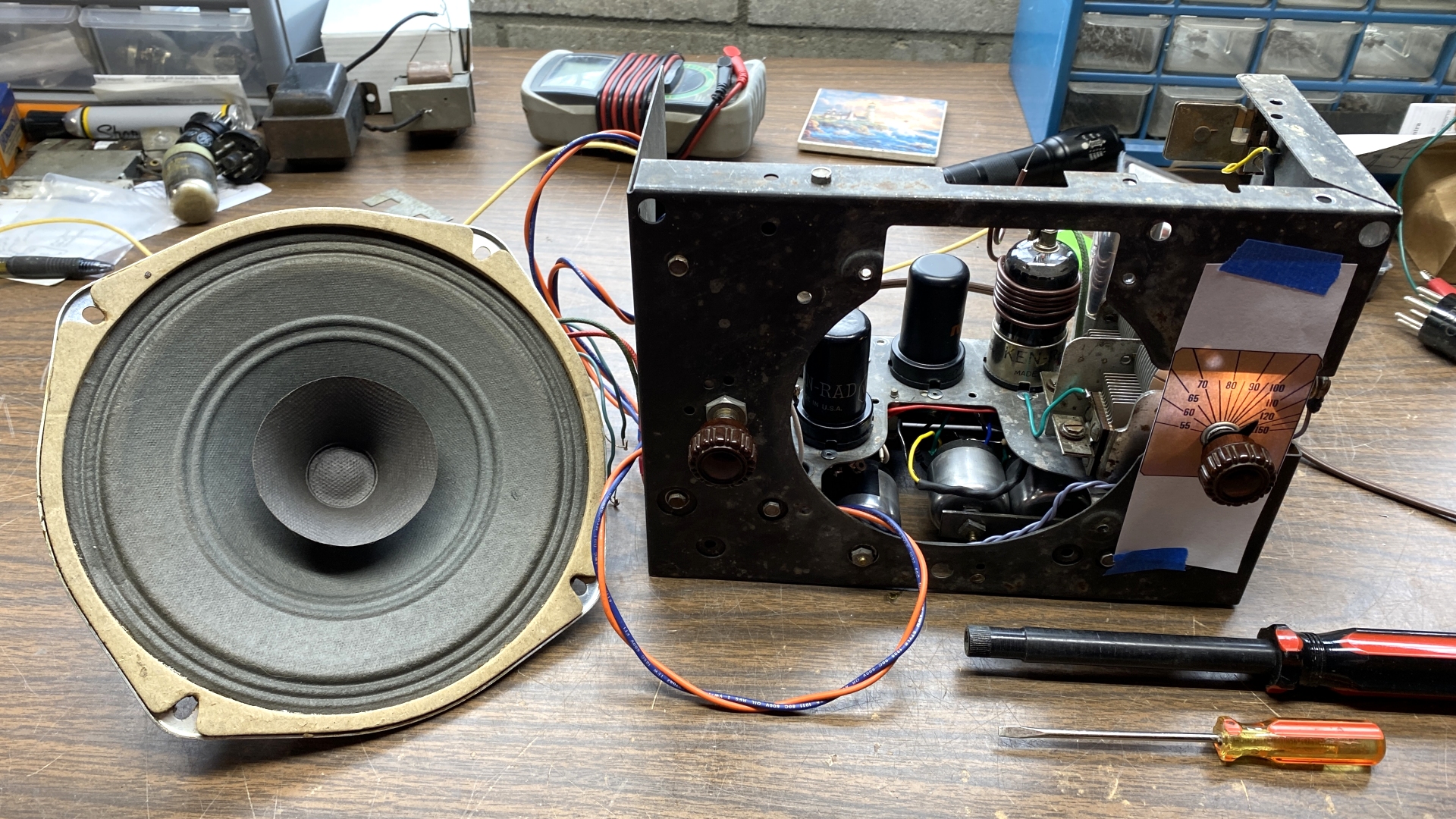
This morning, I printed a 54 dial graphic to size and taped it to the chassis. I found that the alignment - on the high end at least - actually wasn't too far off. At the low end, 600 kc was coming in around 70 on the dial. Fortunately, the 54 has a low frequency padder so this error was soon taken care of.
Now the set has been nicely aligned and is working properly. Yes, it is less sensitive on the low end of the dial, but it seems most of these cheaper radios are anyway. This isn't a laboratory grade instrument - it's a five tube cigar box pee-wee which was originally made to sell at a fairly low price.
I am very happy with how it has turned out. I would absolutely do this conversion again on a 54 if only to get rid of those two large power-wasting resistors on top of the chassis.
Thanks for the responses.

(Notice the Steve Davis alignment tool in the photo above.) 
--
Ron Ramirez
Ferdinand IN
Posts: 1,883
Threads: 120
Joined: May 2008
City: Omak
State, Province, Country: WA
Hello Ron,
That is smart thinking making that Photo copy !
That is wonderful news about getting that Set to work properly and I see no harm in doing that conversion .
Just Like I have a Deltrola Pee-Wee that Late our old ARF member Late Dale gave me it had survived a storm but only chassis survived .
Sincerely Richard
Users browsing this thread: 1 Guest(s)
|
|
Recent Posts
|
|
1949 Motorola 5A9M
|
| This would be the second portable in the "other radios" forum where I have a similar one in my collection. I h...Arran — 12:41 AM |
|
Looking for any info: 1977 Ford-Philco Console Hi-Fi Turntable and Radio
|
| Hi PittsburgTost.
The record changer looks like a Garrard or BSR (Likely Garrard). The spindles just pull out and pu...MrFixr55 — 11:57 PM |
|
Looking for any info: 1977 Ford-Philco Console Hi-Fi Turntable and Radio
|
| Hello PittsburghToast ,
Welcome aboard and it looks like gary may have something for you !
now if I dig through my se...radiorich — 11:35 PM |
|
Model 80 Antenna Issue?
|
| You are kind of on the right path. You can touch the grid cap of the Detector/Oscillator 36 tube. I'm expecting a respon...RodB — 08:48 PM |
|
Looking for any info: 1977 Ford-Philco Console Hi-Fi Turntable and Radio
|
| Welcome to the Phorum, PittsburghToast! I found an old thread that my interest you regarding the quality and worth of P...GarySP — 08:48 PM |
|
Looking for any info: 1977 Ford-Philco Console Hi-Fi Turntable and Radio
|
| Welcome to the Phorum!
:wave:
We do not have anything on that unit in our digital library. There is a Sam's Photof...klondike98 — 08:47 PM |
|
Model 80 Antenna Issue?
|
|
I’ve replaced all the caps and resistors and the radio is working but minimal volume unless I put my hand near the re...Hamilton — 08:24 PM |
|
Looking for any info: 1977 Ford-Philco Console Hi-Fi Turntable and Radio
|
| Hi there! this is my first time posting. I recently picked up this Ford-Philco Console record player and radio at a yard...PittsburghToast — 07:28 PM |
|
philco predicta
|
| I found that where I have the 140v B+ there is 50v and the tuner receives 235v through the orange cablecgl18 — 04:14 PM |
|
Philco 91 code 221
|
| Chassis grounds thru rivets is another good place to look. Oh and the stator screws on the tuning cap where the leads at...Radioroslyn — 08:11 AM |
|
Who's Online
|
| There are currently no members online. |

|
 
|


![[-] [-]](https://philcoradio.com/phorum/images/bootbb/collapse.png)


